G300 Installation Manual – Pinouts
Page A-3
190-00921-01
Revision A
A.1.4
Serial Data
A.1.4.1
RS-232
The RS-232 outputs conform to EIA Standard RS-232C with an output voltage swing of at least ±5V
when driving a standard RS-232 load.
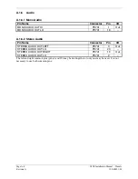
Pin Name
Connector
Pin
I/O
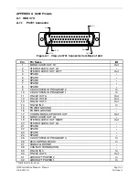
RS-232 IN 1
P3701
47 In
RS-232 OUT 1
P3701
48 Out
RS-232 IN 2
P3701
14 In
RS-232 OUT 2
P3701
30 Out
RS-232 IN 3
P3701
29 In
RS-232 OUT 3
P3701
13 Out
A.1.4.2
RS-422
This data bus conforms to EIA RS-422 standards.
Pin Name
Connector
Pin
I/O
RS-422 OUT A
P3701
11
Out
RS-422 OUT B
P3701
12
Out
A.1.4.3
CAN Bus
This data bus conforms to the BOSCH standard for Controller Area Network 2.0-B. This bus complies
with ISO 11898.
Pin Name
Connector
Pin
I/O
CAN BUS HI
P3701
46 I/O
CAN BUS LO
P3701
45 I/O
CAN BUS TERMINATION
P3701
28 --
A.1.4.4
Configuration Module
Pin Name
Connector
Pin
I/O
CONFIG MODULE CLOCK
P3701
33 I/O
CONFIG MODULE DATA
P3701
50 I/O
CONFIG MODULE POWER OUT
P3701
17 Out
CONFIG MODULE GROUND
P3701
49 --
A.1.5
Lighting
The GDU 37X display and keys can be configured to track 28 VDC or 14 VDC lighting busses using
these inputs.
Pin Name
Connector
Pin
I/O
14V LIGHTING BUS HI
P3701
43
In
28V LIGHTING BUS HI
P3701
26
In
Содержание GMU 44
Страница 1: ...190 00921 01 March 2009 Revision A G300 Installation Manual ...
Страница 36: ...Page 4 8 G300 Installation Manual GSU 73 Revision A 190 00921 01 This page intentionally left blank ...
Страница 44: ...Page 6 4 G300 Installation Manual Antennas Revision A 190 00921 01 This page intentionally left blank ...
Страница 94: ...Page 10 12 G300 Installation Manual Troubleshooting Revision A 190 00921 01 This page intentionally left blank ...


