6
Step 7
– Connecting the power supply
The 12V power supply cable running from the implement module should be connected directly to
the tractor battery or via purpose designed power sockets. Cigarette lighter sockets are not
suitable.
Caution
•
Route the cable carefully ensuring that it cannot become trapped or chaffed.
•
The 20amp fuse at the battery terminal end of the cable is for short circuit protection and
must not be removed.
•
The polarity is denoted by + and
– marker rings on the cables. The fuse is on the + cable.
Step 8
– Start the tractor and console
With the implement still on the ground check that the spool valve is in neutral and all persons are
well clear. Start the tractor then press the console power button which will remain illuminated. Wait
for the system to "boot up" with a few text screens then a graphics start up screen with touch
screen buttons should appear. Press the touch screen button labelled Inter-Row. A new screen
with a live video image will appear, this is referred to as the working screen.
Step 9
– Checking hydraulic operation
Set the tractors hydraulic control to provide a constant flow to the implement with the facility to
disengage the supply immediately should a fault occur.
Once the system has booted up and the working screen is displayed, lift the implement clear of the
ground and engage the hydraulic supply. The side shift or steered discs should centralise.
If the side shift or discs were already central and you wish to test them press the second touch
screen button from the bottom on the right labelled
“manual”. The hydraulic side shift/steering is
now in manual mode and can be operated via the touch screen buttons labelled with left and right
arrows. Each button press steps side shift/steering by 7% of its stroke. Repeated pressing (but
not holding your finger down) will result in continuous travel up to the end of the stroke. This
procedure can be used to check that hydraulic flow is in the correct direction and that the side shift
rate is correct. A normal side shift rate would be 0.1m/s (e.g. 3s to travel a 0.3m stroke). To return
to normal automatic mode press the same button again. The side shift/disc will stay in the position
until the implement is lowered and raised again, or the machine starts to travel forward.
Caution
•
Side shift/disc travel all the way to one side on lifting the implement may indicate that the
hydraulic supply is connected the wrong way.
•
Rapid side shift/disc oscillations back and forth about the central position indicate that the
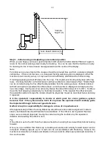
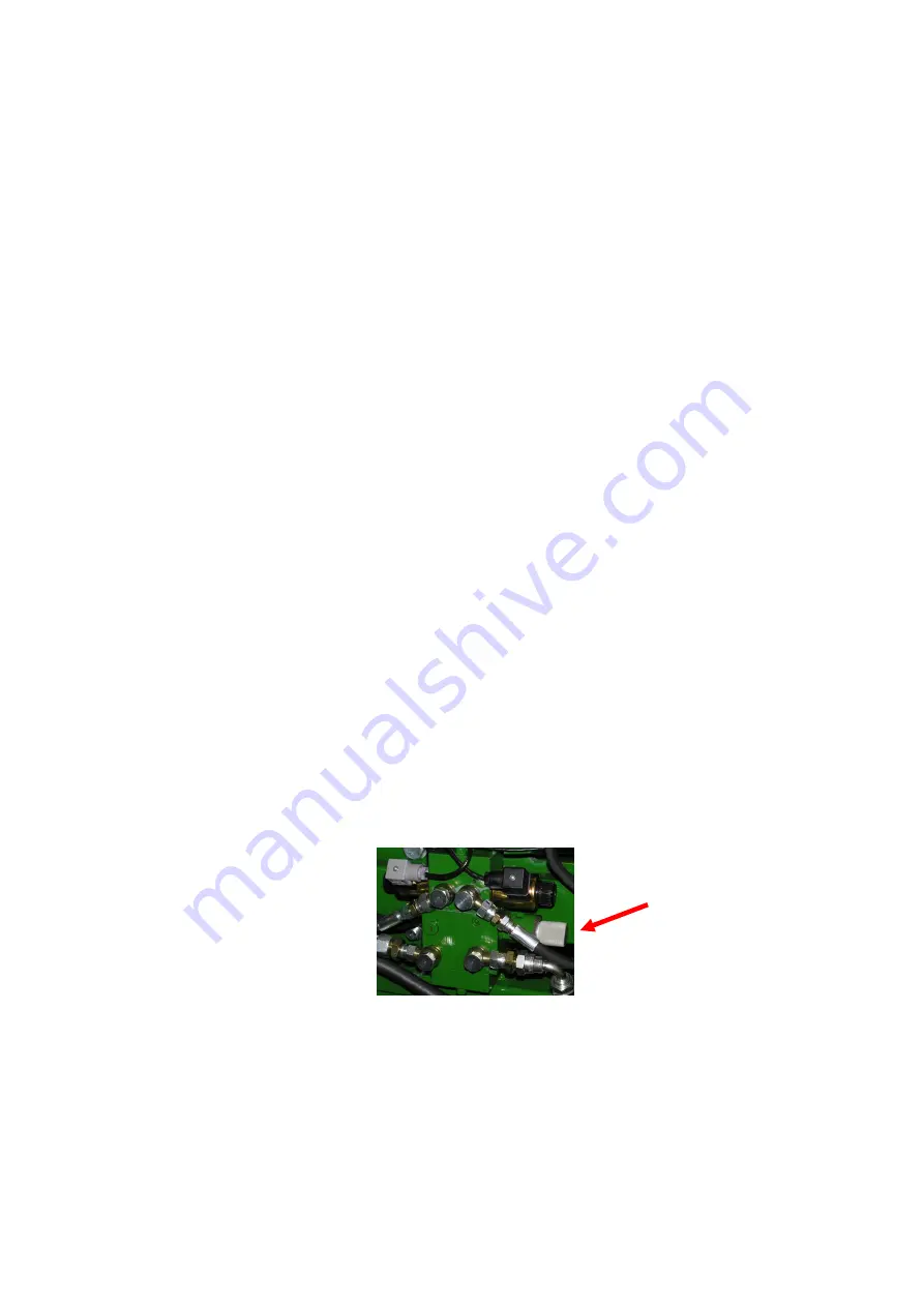
hydraulic flow rate is too high. The tractor flow control should be turned down. Alternatively,
the hydraulic flow control valve on the implement may be adjusted, see picture.
•
Only adjust the flow control valve with the implement on the ground and the tractor engine
switched off.
The machine is now ready for work, though before proceeding to the operational phase it is worth
familiarising yourself with the working screen.

