


5
3. Assembly
The following steps outline how the Robocrop precision guided implement should be set up.
Step 1 - Mounting the console
Mount the console in the tractor cab in a position where it can be clearly seen, but does not
obscure operator's visibility. Four M6 tapped holes at a square 100mm pitch in the rear of the
console facilitate mounting to a bracket. A number of alternative mounting arrangements are
possible, but it is recommended that the chosen method should provide some vibration isolation.
Caution
•
The console should be protected from severe vibration.
•
Do not use longer screws than those supplied otherwise damage to the console may result!
Step 2
– Hitching to the tractor
Position the tractor and implement on a level surface. Check that the t
ractor’s lower link arms are
evenly adjusted and hitch the tractor to the 3-point linkage points on the side shift frame.
Caution
•
The side shift 3-point linkage points are to standard category 2 dimensions and so must be
attached to a similar tractor linkage.
•
Once the 3-point linkage is correctly fitted stop the tractor and apply the handbrake.
Step 3
– Reducing lateral movement
Adjust the stabiliser links to prevent lateral movement of the lower link arms.
Caution
•
For side shifting front mounted systems it is particularly important that there is no lateral
movement in the linkage.
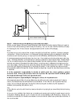
Step 4
– Levelling the implement
With the cultivator on the ground, adjust the top link so that the cultivator is level, front to rear
(camera pole(s) should be vertical).
The control system loom and hydraulic hoses can now be routed from the implement to the tractor.
Caution
•
Clipping the loom and hoses to the top link should keep them clear of catch points.
•
Make sure that the linkage can be operated over its full range without stretching or chaffing
the loom conduit or hoses.
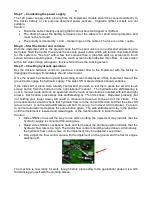
Step 5
– Connecting the hydraulic hoses
Plug the hoses into a suitable double acting valve connection on the tractor. Markers on the hoses
indicate the following:
Supply
–
RED
Return -
BLUE
.
Step 6
– Connecting the implement to the console
The cable/conduit from the implement module should be routed into the tractor cab and through to
the console.
Caution
•
Do not to allow the loom to restrict access to or exit from the cab or act as a trip point.
Plug the multi pin plug into the socket in the bottom of the console.
Caution
•
Note the correct alignment of the tabs in the plug and socket and avoid excessive force in
pushing the connector together.
If you have any problems with this connector consult
your dealer as incorrect assembly may seriously damage the computer
.


