manualshive.com logo in svg
background image

3–600    Page 10

Never tighten liner jack screws while
pump is running. If the screws are
drawn up too tight, enough pressure
can be put on the packing to crush the
liner. This ruins the liner, is apt to ruin
the piston and can cause piston rod
breakage.

Whenever the cylinder head is removed for any reason,
the liner jack screws must be backed out. Jack screws
should be greased to increase life of screws and cylin-
der heads and also to prevent rust formation.

When the cylinder head is replaced, the head to cylin-
der stud nuts should be tightened completely. AFTER
the head nuts are tight, the liner jack screws should be
adjusted against the liners and the locknuts tightened.
Be sure packing is installed under set screw nuts to pre-
vent leakage

Some pumps are equipped with a clamp located
against the end of the liner and serves as a face for the
set screws to bear against. For the proper tightening
torques refer to torque table, page 18.

FLUID END PARTS – Standard procedure for shipping
pumps from the Factory is with valves, pistons, liners,
piston rods and packing installed.  These fluid end ex-
pendable parts are shipped unassembled only when
requested by the customer.

FLUID CYLINDER LINERS – Liners should be
installed in accordance with instructions given under
heading ”Fluid Cylinder Liner Packing”, page 9. Clean
liners thoroughly and grease the outside diameter be-
fore installing. Liner jack screws should be tightened as
uniformly as possible.

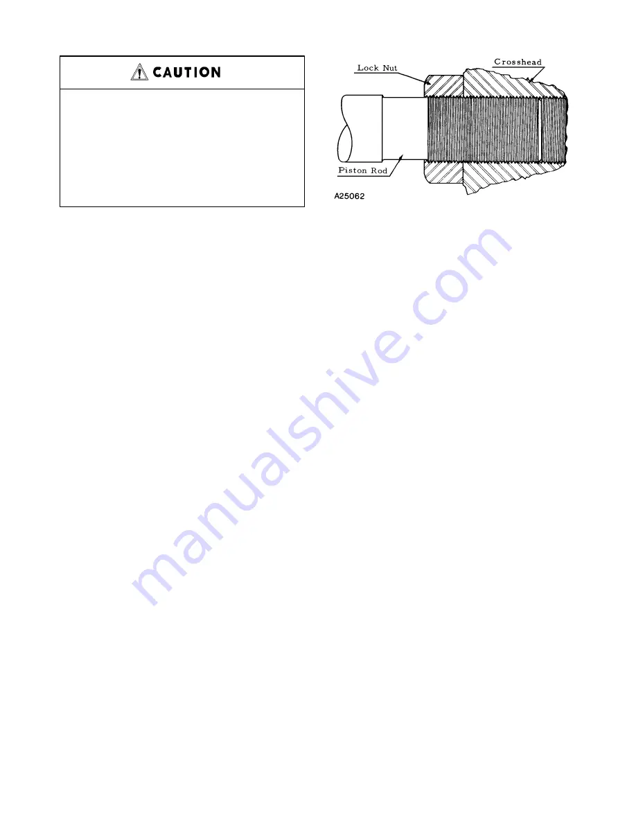
PISTON RODS – Pistons should be assembled on the
rod taper WITH THE THIN NUT NEXT TO THE PIS-
TON HUB AND THE THICK NUT ON THE OUTSIDE.
This is important as the outer nut carries the load. Slush
service rods use one elastic collar–type locknut per
rod. Rods should be threaded into the crosshead as
shown in FIGURE 6, leaving approximately one thread
of the locknut over the relieved portion of the rod as a
protection to the threads.

FLUID VALVES – Valves are easily installed in their in-
dividual valve pots. Care should be exercised to tighten
the valve cover nuts as uniformly as possible, tighten-
ing each nut a little at a time until all are tight. Valve

FIGURE 6  –  PISTON ROD

seats and the bore in the deck must be perfectly clean
and free from oil or grease.

Valve seats can be removed with a puller which can be
purchased from Gardner Denver Machinery Inc.

STARTING A NEW PUMP – Pumps are shipped from
the factory without oil in the crankcase.  The hood
should be removed and the power end examined and
cleaned if necessary. The pump may have been in stor-
age or in the yard for some time and as a consequence
dirt may have entered the crankcase.   Parts may have
been robbed from the pump during storage and not re-
placed. All nuts and screws should be tightened.

The jackshaft bearings have been supplied with grease
at the factory and no grease should be added at this
time, unless bearings have been disturbed.

Be sure all valves in the discharge line are open. No
valve should be installed between the pump and pres-
sure relief valve in discharge line.

To prevent excessive wear on the fluid pistons and
packing when starting, remove a suction valve cover
plate on each side of the fluid end and prime the pump.
Pump should be started slowly, if possible, and should
be operated for several hours with practically no dis-
charge pressure. Check oil level as it may be neces-
sary to add a small quantity of oil to compensate for that
adhering to the walls of the crankcase and the moving
parts. The pump may then gradually be brought up to
full speed and full working pressure. Watch for undue
heating or abnormal noise in the working parts. Check
all joints in the suction line to be sure there are no air
leaks.

Make certain pump is rotating in the correct direction.
Refer to FIGURE 7, page 11.

Содержание FXF - 5"

Страница 1: ...GARDNER DENVER DUPLEX POWER PUMP MODELS FXF 5 FXG 6 FXX 8 FXD 10 FXE 10 OPERATING AND SERVICE MANUAL 3 600 6th Edition June 1997...

Страница 2: ...ump Authorized distributor service technicians are factory trained and skilled in pump maintenance and repair They are ready to respond and assist you by providing fast expert maintenance and repair s...

Страница 3: ...sult in economical operation and minimum downtime Danger is used to indicate the presence of a hazard which will cause severe personal injury death or substantial property damage if the warning is ign...

Страница 4: ...on 3 12 Dimensions Running Clearances Section 4 15 TroubleShooting Section 5 19 Warranty Last Page List of Illustrations Figure 1 Crankcase Oil Requirements 7 Figure 2 Lubrication Fill Rate 8 Figure 3...

Страница 5: ...et or Suction Piping 7 Fluid Piston Rod Baffle 9 Fluid Piston Rod Packing 9 Fluid Pistons and Packing 8 Fluid Valves 10 Foreword ii Frame Oil Stop Head Packing 9 FXE Main Gear and Eccentric 13 Hammer...

Страница 6: ...TIONS SECTION 3 12 Service Abrasive High Pressure Pistons 9 Boiler Feed 8 Clean Oil or Petroleum Products 9 High Pressure Special Fluid 8 High Temperature 9 Low Pressure Water 8 Specifications Torque...

Страница 7: ...ions and instructions contained in these manuals If any of these documents are lost or become illegible they must be replaced immediately The danger no tices plus the operating and service manuals sho...

Страница 8: ...by trained experienced operators who are physically and mentally prepared to devote full attention and alert ness to the moving and lifting operations An operator should be fully aware of the use capa...

Страница 9: ...s charge line and not at the opposite end of the discharge manifold in a dead end connection The dead end may become clogged with solid material carried in the fluid which could prevent proper relief...

Страница 10: ...pump systems Block the crankshaft from turning and make certain that all pump drive motor or engine start switches or starter controls are clearly tagged with warnings not to start the pump while rep...

Страница 11: ...and all electrical components and wiring must meet the current National Electrical Code for explosive atmosp heres These precautions must be taken to avoid possible per sonal injury death and or equi...

Страница 12: ...r connect any equipment to the system which has a rated or tested pressure capability be low the system operating pressure The equipment must be shut down and the system pressure released before chang...

Страница 13: ...isable to use an am ple size discharge line to prevent excessive friction The use of an air chamber is recommended and ample size chambers are available for all pumps RELIEF VALVE Pump must be protect...

Страница 14: ...fittings A reliable multipurpose FIGURE 3 PACKING TYPE PISTON grease NLGI Grade No 2 should be supplied to these with discretion Roller bearings WILL HEAT IF TOO MUCH GREASE is used especially if bear...

Страница 15: ...is standard for water oil and general service Maxi mum service ratings for this packing are 250 PSI and 250_ F Molded convex packing is standard for mud service Maximum rated service temperature is 1...

Страница 16: ...ing approximately one thread of the locknut over the relieved portion of the rod as a protection to the threads FLUID VALVES Valves are easily installed in their in dividual valve pots Care should be...

Страница 17: ...3 600 Page 11 FIGURE 7 ROTATION OF ECCENTRIC PREFERRED ROTATION OF ECCENTRIC...

Страница 18: ...shings are pressed on the jackshaft and need not be removed unless replacement is necessary The jackshaft can be lifted clear of the gear teeth and removed The jackshaft is not interchangeable end for...

Страница 19: ...d wood block The bearing cone and seal sleeve on the side opposite the tapped hole will slip off the shaft To Install Main Bearings For All Pumps 1 Install eccentric with gear teeth in correct positio...

Страница 20: ...rom Gard ner Denver Machinery Inc OPERATING SPEEDS AND PRESSURES See bul letins for operating speeds and pressures for type of service All displacements are theoretical with piston rod vol ume deducte...

Страница 21: ...meter Diameter Stuffing Box End End Model Type Inches mm Inches mm Inches mm Inches mm FXF ALL 4 x 5 101 6 x 127 0 15 16 23 8125 1 3 4 44 45 2 1 16 52 3875 FXG ALL 5 x 6 127 0 x 152 4 1 25 4 1 13 16 4...

Страница 22: ...occurs b CONNECTING ROD LINER TO ECCENTRIC Actual 011 022 279 559 009 017 229 432 Feeler Gauge 010 021 254 533 008 016 203 406 Condemnable when liner knocks or clearance equals 040 1 016 035 889 c CR...

Страница 23: ...b CONNECTING ROD LINER TO ECCENTRIC Actual 007 015 178 381 006 014 152 356 Feeler Gauge 006 014 152 356 005 013 127 330 Condemnable when liner knocks or clearance equals 030 762 030 762 c CROSSHEAD P...

Страница 24: ...uid Cylinder 590 81 6 Head Stud Nut Fluid Cylinder Liner 25 3 5 25 3 5 25 3 5 25 3 5 Set Screw Suction Manifold to 260 36 0 Fluid Cylinder Discharge Manifold to 260 36 0 Fluid Cylinder Suction Manifol...

Страница 25: ...in drive c High back pressure d Piston rings in fluid end binding e Pistons improperly packed f Valves not holding g Leakage past fluid piston rings h Leakage past liner packing i Liners worn PUMP LO...

Страница 26: ...or shall be limited to the amount specified in the Company s labor rate schedule Labor costs in excess of the Company rate schedules caused by but not limited to location or inaccessibility of the equ...

Страница 27: ......

Отзывы: