background image

TR-RC1xx - User Manual

7.6

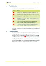
Fault detection

The TR-RC can detect a range of errors when connected to a light. The
displayed error codes are shown below with their reasons.

Error

Reason

PO

Internal power dissipation is too high. Output turned off.

OP

Output current to lighting is too low. The light is open circuit
or there is not enough supply voltage for the requested out-
put current.

SH

Output voltage is too low. The TR-RC detects that the out-
put is short-circuited.

HI

The voltage required for the lighting has increased too
much. Check for ageing of the light or a failed LED.

LO

The voltage required for the lighting has decreased too
much. Check for ageing of the light or a failed LED.

Note:

When the output current falls below 100mA, some fault detection is

disabled. Press

SEL

to cancel the error and allow the TR-RC to sense the

light again.

7.7

Factory settings

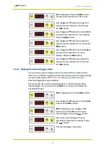
You can clear the TR-RC configuration to return it to its factory settings:
The lighting rating is cleared and the light does not illuminate.

Clear the configuration from the front panel by pressing and holding

SEL

and

q

for about 5 seconds, until

COL

is displayed. You can also clear the

configuration by using the

CL

command (see

Section 10.3.3, General

commands

).

You can start the TR-RC from a powered down state (cold boot) with the
front panel keypad locked; this process removes the keypad lock.

16

Содержание GigE Vision TR-RC Series

Страница 1: ...TR RC120 122 LED Lighting Controllers Issue 004 User manual www gardasoft com...

Страница 2: ...annot cause any dangerous situation or significant financial loss to occur Deliberate acts of endangerment and vandalism are not covered by this document and must be considered by the installer While...

Страница 3: ...R RC 8 5 1 Environmental considerations 8 6 Connecting the TR RC 9 6 1 Power 9 6 2 Lighting output 9 6 3 Trigger input 10 6 4 Ethernet 11 6 5 Connectors general 11 7 General description 12 7 1 Pulse a...

Страница 4: ...nternal trigger timer 27 10 2 8 Using the key lock 28 10 2 9 Viewing the trigger status 29 10 2 10 Viewing the output current 29 10 3 Ethernet commands 30 10 3 1 Ethernet communication 30 10 3 2 Comma...

Страница 5: ...TR RC has Ethernet connectivity and may be controlled through a web portal and using triniti technology allows the control of your illumination system if it is triniti enabled The TR RC automatically...

Страница 6: ...tally touch it and ensure there is a free flow of air around the unit 2 2 Electrical The TR RC produces high energy pulses Take care to connect the outputs correctly and protect the output wiring and...

Страница 7: ...specific to each installation While Gardasoft Vision Ltd has taken every care in the preparation of this advice Gardasoft Vision Ltd and Gardasoft LLC accept no liability for damages of any kind exce...

Страница 8: ...rper mehr als 65 C erreichen und folglich bei Ber hrung Verbrennungen verursachen Positionieren Sie sie an einem Ort an dem sie nicht aus Versehen von Personal ber hrt werden und an dem die Luft um d...

Страница 9: ...tungsausschluss Diese Angaben dienen lediglich der Orientierung Der Monteur muss f r jede Installation eine eigene spezifische Risikobewertung durchf hren Gardasoft Vision hat bei der Zusammenstellung...

Страница 10: ...ent d passer 65 C ce qui est suffisant pour occasionner des br lures en cas de contact Assurez vous que le personnel ne peut pas y toucher accidentellement et que l air circule autour de l unit 4 2 le...

Страница 11: ...en tre alt r e 4 4 Clause de non responsabilit Ces informations sont seulement titre indicatif Les installateurs doivent tablir leur propre valuation de risques pour chaque installation Gardsoft Visio...

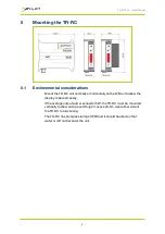
Страница 12: ...the DIN rail to allow the display to be read easily If the average output power exceeds 15W the TR RC must be mounted vertically to allow air to pass through it Leave 25mm clear either side of the TR...

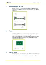
Страница 13: ...ty Extra Low Voltage SELV output Route low voltage wiring to the TR RC controller separately from mains electricity wiring If this is not possible make sure the low voltage wiring has an insulation ra...

Страница 14: ...not be commoned to any other controllers or grounded in any way The lighting output connections are shown below 6 3 Trigger input The trigger input is a Smart Input it accepts a range of trigger sour...

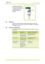
Страница 15: ...s at 10MBits per second 6 5 Connectors general The connectors required to mate with the TR RC controller s connectors are as follows Connector Description Suppler Part number Power input W rth 351 ser...

Страница 16: ...ss can be set up to 1000 of its rating for short periods and low duty cycles To avoid damage to the lighting the TR RC limits the duty cycle by ignoring triggers that are too soon after the previous t...

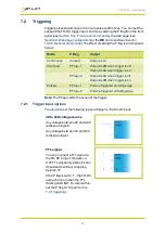
Страница 17: ...Output is on when trigger is off Output is off when trigger is on Pulsed P Flag 1 Pulse is triggered on rising edge P Flag 0 Pulse is triggered on falling edge Note The P flag inverts the sense of th...

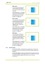
Страница 18: ...this set the P flag to 0 see Section 7 2 Triggering PNP signal You can connect a PNP open collector drive to the TR RC s input Use the connections shown opposite The PNP transistor should not pull up...

Страница 19: ...mation on this feature see the application note APP966 SafePower Technology available from www gardasoft com Downloads 7 5 Flags You can set flags on the TR RC controller to alter its operation They c...

Страница 20: ...he voltage required for the lighting has decreased too much Check for ageing of the light or a failed LED Note When the output current falls below 100mA some fault detection is disabled Press SEL to c...

Страница 21: ...ler 8 1 IP address The TR RC needs an Internet Protocol IP address to communicateover Ethernet There are two ways to get an IP address either programmed into the unit or using DHCP For DHCP mode the T...

Страница 22: ...roperties iv From the list select Internet Protocol TCP IP press Properties If Obtain an IP address automatically is set then DHCP is probably used However there may be an alternative fixed IP address...

Страница 23: ...P address displayed in GardasoftMaint into your web browser which will display the Main page GardasoftMaint software is available from www gardasoft com Downloads 9 1 Main page The main page shown bel...

Страница 24: ...the measurements the TR RC makes during operation You can set the mode continuous pulsed or switched the light s brightness and pulse settings You must click the Submit button to effect any changes y...

Страница 25: ...al 9 3 General setup page On the general setup page shown below you can set a password for the TR RC and send it commands Refer to Section 10 Configuration commands for the commands you can use to ope...

Страница 26: ...n be set from 0 01A to 2 0A for the TR RC120 or 0 1A to 10A for the TR RC122 in steps of 0 01A The voltage rating can be set from 12V to 24V in steps of 1V When a voltage rated light is connected the...

Страница 27: ...ut no rating specified To configure the TR RC from the front panel press and hold SEL for 1 second CH1 is displayed You can then use the p and q keys to scroll through the menu pressing the SEL button...

Страница 28: ...in Amps or the voltage in volts Press the SEL button The light s rating is set up 10 2 3 Setting up continuous output Press and hold SEL for 1 second and follow the keystrokes below CH1 is displayed...

Страница 29: ...p and q buttons to set the Trigger flag F P is enabled F P is disabled Press the SEL button Use the p and q buttons to set the Error Detect flag F E is enabled F E is disabled Press the SEL button Sw...

Страница 30: ...ess to more than 100 the pulse width is limited to a safe value as described in Section 7 1 Pulse and duty cycle limits 10 2 6 Setting time periods When the TR RC requires you to enter a numeric value...

Страница 31: ...7 Setting the internal trigger timer You can set an internal trigger timer when the TR RC is in pulse mode When set the TR RC triggers with the same delay and pulse width already set up as described...

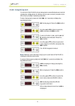
Страница 32: ...lock code use the p and q buttons to scroll to Lc Press the SEL button Use the p and q buttons to set a lock code value from 0 to 255 and press the SEL button The TR RC keypad is locked Note Setting...

Страница 33: ...Viewing the output current You can view an approximate measure of the output current from the TR RC front panel The current measurement is updated roughly once per second but this can be slower when t...

Страница 34: ...en A carriage return ASCII 13 character must be sent to terminate the command line in case multiple TCP packets become joined 10 3 2 Command structure Commands are sent by the host a PC connected to t...

Страница 35: ...separated by a comma Time periods are specified in milliseconds by default but you can add s ms or us to the parameter to specify seconds milliseconds or microseconds Current is specified in amps by d...

Страница 36: ...ated set the current rating to 0 Set continuous mode This command sets the output to continuous mode and allows the brightness to be set RS1 s Where s brightness as a percentage 0 to 100 Set pulse mod...

Страница 37: ...Set the internal trigger These commands control the internal trigger When set the output is triggered using an internal trigger signal Type in TT0 to disable the internal trigger TT1 to enable the in...

Страница 38: ...0 000A Where see overleaf CH Channel number this is always 1 MD Mode 0 continuous 1 pulsed 2 switched S Percentage brightness 50 0 50 the second part is always 0 0 DL Pulse delay PU Pulse width RT Ret...

Страница 39: ...3 Event codes Clear any errors Use this command to read the last event or error code when Ethernet messaging has been disabled GR Any error displayed on the TR RC is cleared If this was a lighting err...

Страница 40: ...C s settings using Ethernet commands and through its web page The settings of this command are restored after a power cycle 10 4 Command summary Command Example Effect AW AW Save changes CL CL Clear c...

Страница 41: ...RC1xx User Manual Command Example Effect KB KB1 23 Disable the keypad buttons on the front panel Set the unlock code to 23 TR TR1 Generate one trigger pulse ST ST Show the unit s configuration details...

Страница 42: ...ulsed Pulsed output average power Max 25W Max 30W Trigger input Smart input compatible with 3V 24V TTL NPN and PNP Input Impedance nom 8kohms Pulse timing From 100 s to 100ms in steps of 100 s Delay f...

Страница 43: ...t is 2A for the TR RC120 and 10A for the TR RC122 11 2 3 Pulse mode The maximum pulsed output current is 2A for the TR RC120 and 10A for the TR RC122 When operating at high currents even if you set a...

Страница 44: ...to 127 An error has occurred See Section 11 4 Error codes 128 A light has been connected and is working 129 A light has been connected but does not have a current or voltage rating 130 FAT An over tem...

Страница 45: ...d Err 9 20 Settings could not be saved to EEPROM Err 19 A light has been connected but no rating has been set Err 21 23 A sensing error has occurred see Section 7 6 Fault detection Err 22 FAA The ligh...

Страница 46: ...41 45 FAC Fatal error The unit is outputting more current than expected Err 42 SH The output current is too high Err 43 OP The requested output current requires too high a voltage Err 44 FAt Fatal err...

Страница 47: ...TR RC1xx User Manual 43...

Страница 48: ...yright 2017 Gardasoft Vision Ltd Gardasoft Vision Ltd Trinity Court Buckingway Business Park Cambridge CB24 4UQ UK tel 44 1954 234970 fax 44 1954 231567 Gardasoft LLC Oak Ridge Road Weare New Hampshir...

Отзывы: