TR-RC1xx - User Manual
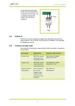
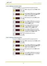
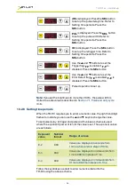
NPN signal
You can connect an NPN open
collector drive to the TR-RC’s
input. Use the connections shown
opposite.
If the P flag is set to ‘1’ the TR-RC
output turns on when the driving
transistor turns on. To reverse
this, set the P flag to ‘0’. (see
).
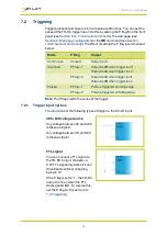
Opto-coupler
You can connect an opto-coupler
as an NPN drive to the TR-RC’s
input. This prevents a ‘ground
loop’ and reduces spurious
triggering in high-interference
environments.
If the P flag is set to ‘1’ the TR-RC
output turns on when the driving
transistor turns on. To reverse
this, set the P flag to ‘0’ (see
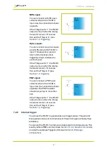
PNP signal
You can connect a PNP open
collector drive to the TR-RC’s
input. Use the connections shown
opposite. The PNP transistor
should not pull up to more than
24V.
If the P flag is set to ‘1’ the TR-RC
output turns on when the driving
transistor turns on. To reverse
this, set the P flag to ‘0’ (see
).
7.2.2
Internal trigger
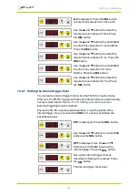
You can set the TR-RC to generate its own trigger pulses. The period of
these pulses can be set in increments of 100µs from approximately 10µs
to 5000ms.
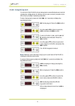
You can set the TR-RC to produce a single pulse for testing purpose. This
is set by either a
TR1
command (see
Section 10.3.3, General commands
)
or using the webpage Trigger button (see
).
—
14
—


