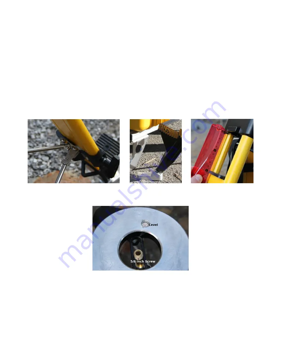
be rotated to permit insertion of the rod. Once the rod is attached, rotate the arm back over the
rod ends and it will lock into place.
2. The tripod legs are numbered 1,2, and 3 with label. Make sure that you note the location of each
leg so that when you return to the site, the orientation of the tripod is identical. One leg of the
tripod should remain fully retracted and this should not change. In sloping terrain, this leg
should be the leg with the highest elevation. The zero degree look direction of the radar is in the
direction of leg 1.
3. Using the bubble level on top of the tripod, extend the other 2 feet of the tripod until the tripod
top surface is horizontal. Remember to keep one leg of the tripod fully retracted and only
extend the other 2 legs.
4. Screw the feet through the hole in the tip to the ground using anchor screws (6mm anchors).
5. Measure and note the extension of the legs for future repositioning.
Figure 2: Fixature of rods to have tripod
legs at fix distance.
Figure 3: Tripod foot with
special tip that allows
screwing to the ground.
Figure 4: Tripod leg extent
documentation.
Figure 5: Interface Plate of the Leica
Tripod with level and 5/8" screw.
3.1.2 Motor with leveler and tower
1. Mount the rotary positioner and leveling assembly on the tripod using the black 5/8” screw
interface of the tripod. The positioner has labels with the numbers 1 and 3. Position this edge of
the posileveler between tripod legs 1 and 3. Rotate the positioner and leveler assembly
such that the edge of the positioner plate is parallel with the tripod stainless-steel rod between
legs 1 and 3.


