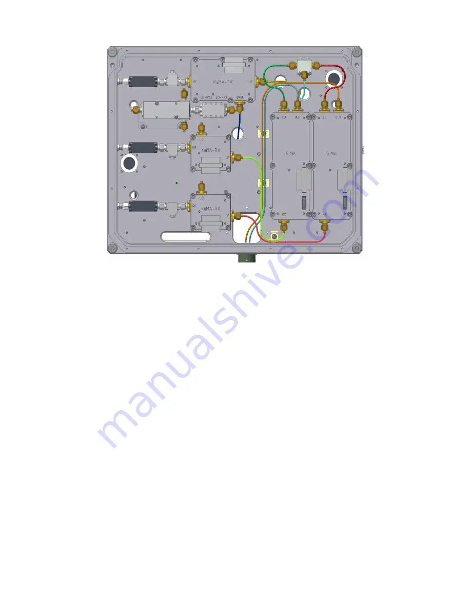
Figure 26: RF Electronics Assembly Interior showing
KuMA-TX and KuMA-RX modules along with the SIMA.
The microwave up- and down converters and IMA are located on one side and the GPS receiver,
CHUPA and DISTRI on the opposite side of the enclosure.
Controller and Power Unit
The control and power unit (Figure 27) contains the power supplies that convert 100-240 VAC or 18-32
V DC to the voltages required by the radar. The power input connector can either have AC or DC input
power. An internal switch can be used to select the input power source. LED lights indicate that power
is available and that the computer communication has been established. Output connectors are provided
for the RF electronics and the azimuthal scanner. Additional ports for Ethernet and USB interfaces are
also available.
The instrument controller and power unit contains a 2.8 GHz Intel Core 2 Duo Processor T9600 on a
Kontron KTGM45 mini-ITX form-factor CPU board with 4 GB RAM and 500 GB SATA disk. An
ATMEL micro-controller switches the PC, GPS, and RF assembly power, monitors temperatures, and
drives the stepper motor controller. The micro-controller is integrated on a single board along with the
power supplies for the Linux computer, azimuthal scanner, internal fans, and USRP2 SDR. Input to the
power supply is 100-240 VAC, or +18 to +32 VDC.
Two internal fans circulate the air inside the Pelican case and transfer heat to 2 external heat sinks, one
on the under-side of the Pelican case and the top cover. The internal fan speed is be regulated to
provide some control of the internal temperature. A goal for temperature regulation is that the internal
temperature is in the range of 0-45 C. The heat transfer out of the case is about 4-5 W/deg. Given the
maximum electronics thermal load, the interior temperature of the case is 15-20 deg C higher than the
external temperature.


