3.1.4 Antenna
1. Take each antenna out of the tube by loosening the 2 thumb screws. NOTE it is important that
you push them out with the antenna cable plug in front to avoid damaging the antenna cable.
2. Mount the antennas one by one on the corresponding antenna holders. Make sure you use a fix
order for the antennas (TX, RX1, RX2) to avoid phase effects due to slightly different antenna
characteristics. It is recommended that you note the serial numbers of each antenna and if it is
the top (TX), center (RX1), or bottom (RX2) of the tower. Each antenna has a slightly different
pattern and phase and so it is strongly recommended to use the same antennas for TX, RX1, and
RX2 for each measurement.
3. Plugin the 3 antennas to the appropriate port on the side of the RF assembly. The antenna cables
have quick-connect SMA connectors. It is very important that these be pushed on gently and
without being tilted relative to the connector axis or else they will be damaged. Inspect the
connector before each use to make sure all the connector gold springs are not damaged or bent.
!! Never detach the antenna holders as you might loose the alignment precision of the antennas. These
have been precisely positioned on the tower to insure that the antennas are parallel
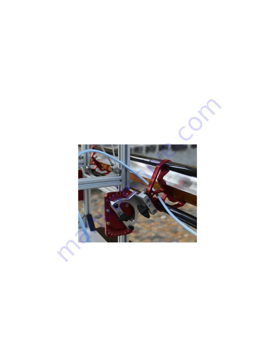
Figure 10: Closeup of the Antenna holder and
Elevation Angle setting.
3.1.5 Instrument Controller and Power Unit
1. Place the Pelican case close to the tripod at a dry and convenient place. The feet can be screwed
to the ground if necessary.
2. Make sure the Instrument Controller is switched off.
3. Connect the Instrument Controller with the RF Unit (orange cable).
4. Connect the Instrument Controller with the motor (2 cables).
5. Connect the Instrument Controller to the network. The controller decides depending on the
traffic which net configuration will be selected.


