background image


Version 1, 21 August 2019, 5 of 21 


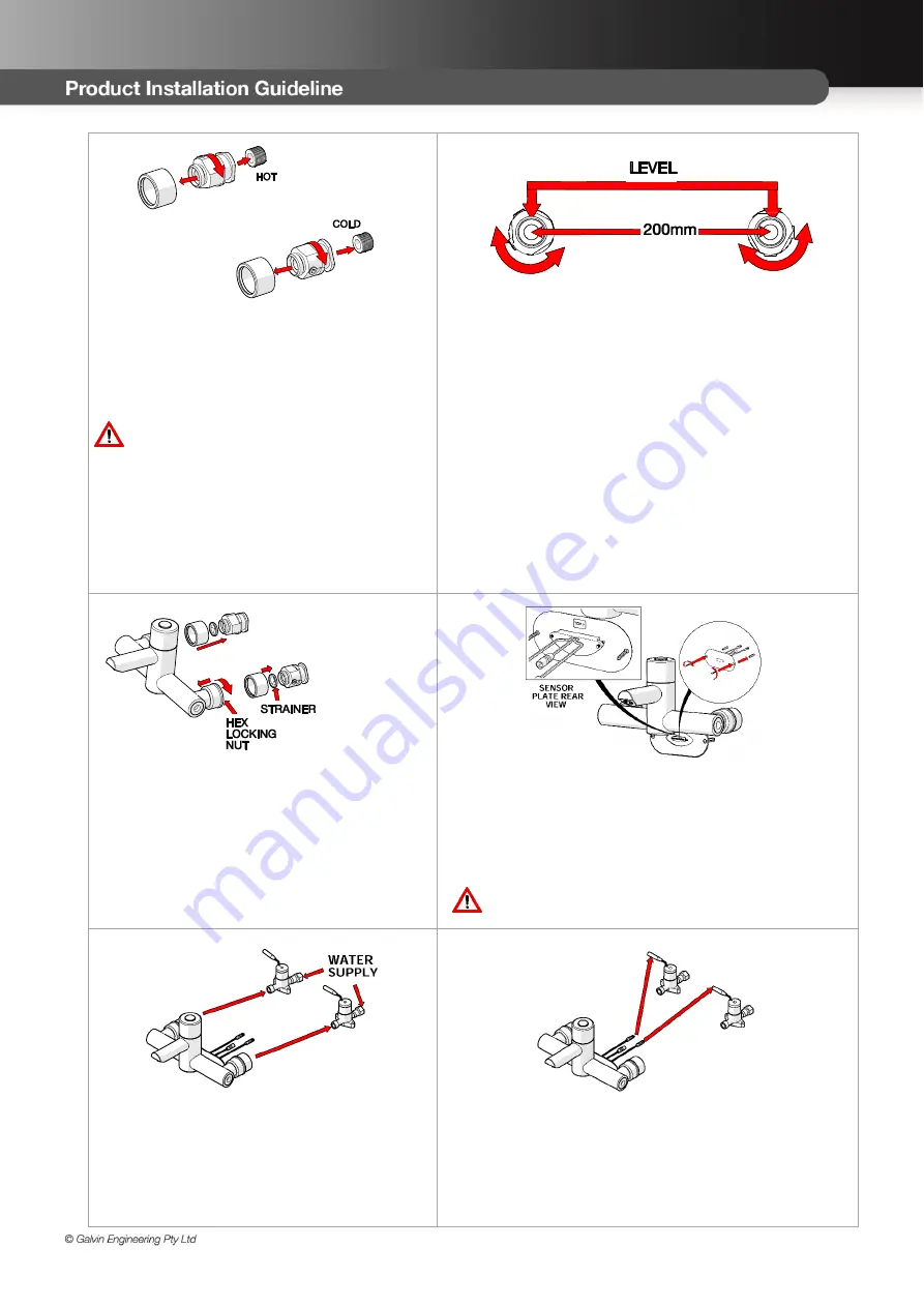
1. Fit isolator connector 


Ensure  /2” male hot and cold water 
supply outlets are positioned as per 
mounting details (section 4.0) at the 
desired height and location above the 
basin/sink.  

Note: Hot supply should be on the left 
when facing the wall 

Remove both isolator connectors from 
box. 

  Remove chromed sleeve from the 

connectors 

  Apply thread tape to the male threaded 

outlets and fit the isolator connectors.


2. Adjust the connectors 

  The isolator connectors are offset to p/- 

15mm of rotational adjustment. 

  With the use of a spirit level and tape measure, you 

are required to  


Position the back of the bases within 3mm of 
the finished wall and; 


Ensure the bases are level and; 


Achieve 200mm centre to centre of the 
connectors 

Note: The use of thread tape is recommended to 
ensure bases stay in the required position and are 
water tight.


3. Fit progressive mixer 

  Fit chrome sleeves to fitted isolator 

connectors. 

Tighten loose nuts on the body to the isolator 
connectors already on the wall ensuring the 
strainer seal is in between.  Do not over 
tighten.


4. Secure Sensor 


Install the proximity sensor to the wall


Ensure correct orientation of the sensor, It is 
critical (see back of the face plate for orientation 
arrow) 

Do not remove the black label in front of sensor 
faceplate until the tap is to be commissioned.


5. Fit solenoids 

  Connect solenoids to the tap and mains 

water line 

Ensure water is connected to correct inlet as 
marked on tap.


6. Connect solenoids 


Connect the solenoids to the sensor.  

The unit supplied with a 3 x 3.2metre extension leads for 
connecting to transformer, solenoid, and sensor.


Содержание CliniMix Lead Safe 100.30.79.00

Страница 1: ...s designed to comply with AS4032 Thermostatic Mixing Valves Materials Design and Performance Requirements The mixing valve has the following features Complies with the requirements of AS4032 4 Thermostatic Mixing Valves Provides high stability of mixed water temperature even under changing inlet conditions Ensures rapid shut down of mixed outlet flow in the event of hot or cold water supply failur...

Страница 2: ...with proximity sensor These are designed to provide water in stable temperature for hand washing This mixing valve is supplied with integral isolating valves strainers check valves and flow regulators and is provided with a facility for thermal disinfecting of the cold inlet side and mixed water outlet for the wall mounted version only The hot side of the body and the inlet is insulated to ensure ...

Страница 3: ...in with proximity sensor Preset line purge feature interval 12 hours after last flush water flow duration 3 min Preset continuous run 5 min Sensor range Sensor1 and Sensor2 custom made steps 5 0 WATER SUPPLY CONDITIONS 5 1 INTRODUCTION This progressive sequential thermostatic mixer with proximity sensor is manufactured to the highest standards and has approval to AS4032 4 which permits it to be in...

Страница 4: ... in AS NZ3666 and local legislation shall be adhered to If the valve is not installed correctly then it will not function correctly and may put the user in danger It may also void the warranty of the valve Prior to the installation of the valve the system must be checked to ensure that the system operating conditions fall within the recommended operating range of CliniMix Progressive Thermostatic ...

Страница 5: ...eve 200mm centre to centre of the connectors Note The use of thread tape is recommended to ensure bases stay in the required position and are water tight 3 Fit progressive mixer Fit chrome sleeves to fitted isolator connectors Tighten loose nuts on the body to the isolator connectors already on the wall ensuring the strainer seal is in between Do not over tighten 4 Secure Sensor Install the proxim...

Страница 6: ... and symbols Touch function Hand object within sensor area Water flows LED flashes Green Water flow stops LED flashes Red H hours min minutes sec seconds FUNCTION PROCEDURE FEEDBACK SIGNAL INFORMATION DEFAULT SETTING RANGE Via IQUA Touch First startup After installation 1x app 4 sec till Remove hand object from sensor area wait 2x sec keep out of sensor area wait till 1x Confirmation ready for ope...

Страница 7: ...x 40x according to setting line purge feature activate deactivate Automatic flush on set interval time of waterflow 3 min 1x app 2 sec till 1x extended function mode is active 12h Off 12 h 24 h 48 h 1x app 25 sec till 1x 4x 1x off 2x 12h 3x 24h 4x 48h ignore flashes after 5 sec and 10 sec keep touched till 1x 4x after app 25 sec releasing defines interval Wait till 1x Confirmation ready for operat...

Страница 8: ...utting off the hot and cold supplies while the mixer is set in the full hot position Shut Down Test 1 With the mixer still on and with both supplies turned on allow the mixed water temperature to stabilise for at least 15 seconds and note the outlet temperature While holding a digital thermometer in the outlet flow quickly isolate the cold water supply to the valve The outlet flow should quickly r...

Страница 9: ...lushing procedure care should be taken to prevent water damage occurring to the surrounding area t is a requirement of AS3500 4 2 that Each thermostatic mixing valve shall have an isolating stop tap valve line strainer and non return valve fitted to the hot and cold water supply lines The inlet fittings supplied with each TMV will ensure this requirement is met If the CliniMix Progressive Thermost...

Страница 10: ...e results are to be compared against original commissioning settings If there are no significant changes at the mixed temperature outlet then a 6 monthly servicing cycle may be adopted Otherwise servicing checks should be carried out more frequently e g every 4 months Follow the recommended maintenance procedures detailed in section 10 During servicing note the following 1 Repeat the procedure of ...

Страница 11: ...red can now be re installed by screwing into the mixer body until it reaches a firm stop and tightened Re fit the cover and re commission the mixer as per commissioning procedure When service is complete slowly open the cold water isolation valve and inspect mixer body for leaks Repeat with hot water isolation valves Commence commissioning process Annual Maintenance Procedure Every 12 months the t...

Страница 12: ...ower supply from proximity sensor 2 Remove top cap screw and cover 3 The setting rings are located either side of the tap stop to stop movement of the tap spindle 4 Remove both rings and turn tap spindle till desired temperature is achieved 5 Reposition both rings on either side at the tap stop so that the tap spindle cannot move 6 Refit the cover the screw and the top cap 10 2 Removal and inspect...

Страница 13: ...tion 10 1 6 After fitting the new cartridge start the test procedure from the section 7 0 on commissioning Record the mix temperature 10 3 Important notes on debris Although this product is protected by built in filters debris can still find its way to the thermostat housing area This can happen during servicing for example Remove cartridge see section 10 2 and carry out an inspection 10 4 Mainten...

Страница 14: ... isolation valves through 90 anti clockwise see picture 1 below 4 Unscrew the two plugs see picture 2 elow and fit the two 3 x fittings from the Disinfection kit WM PMDK Fit the supplied flexi hose between these fittings see pictures 3 and 4 below 5 Now turn the hot isolation valve clockwise see picture 5 below 6 Turn on the mixer Hot water will now pass from the hot inlet through the by pass hose...

Страница 15: ...f the fitting the strainer elements should be checked and cleaned in accordance with the commissioning and servicing guide See section 7 and 9 To access the strainer element first slide forward the shrouds and close the isolation valves Unscrew the connection nut using metric spanner 30mm and detach the unit from the wall See section 9 2 for the assembly drawing to locate the strainer The strainer...

Страница 16: ...that system must be in accordance with its manufacturer s recommendation the Code and all relevant statutory and local State or Territory requirements 4 The valve must be returned to Galvin Engineering together with a fully and correctly completed Galvin Engineering Warranty Claim Form 5 Where the valve is replaced under warranty the replacement valve carries a new warranty as detailed herein Excl...

Страница 17: ...down The hot to mix temperature differential is not 10 C or greater Thermostatic cartridge contains debris or is damaged Non return devices are damaged Raise hot water temperature Clean the cartridge ensuring that all debris is not jammed Clean if necessary Mix temperature unstable Flow rate below 6 L min Thermostatic cartridge contains debris or is damaged Strainers contain debris Non return devi...

Страница 18: ..._____ Temperature of Cold Water to the Valve ________________ Hot Water Pressure ________kPa Cold Water Pressure _______kPa Make of Mixing Valve _______________________ Model No ________________________ Size __________ Valve Location Building _____________________________________________________________________ Valve Identification No _______________________________________________________________...

Страница 19: ... is hereby certified that all the commissioning work has been carried out by the undersigned in accordance with the requirements of the Codes of Practice indicated prior Date of Valve Commissioned __________________________________________________________________________ Name of Licensed Plumber _______________________________ License Cert No ______________________ License Plumbers Signature _____...

Страница 20: ...arm Water C One Outlet in Use All Req d Outlets in Use One Outlet in Use All Req d Outlets in Use 1 2 3 4 5 6 7 8 9 10 11 Give details of brand and model designation Commensurate with the design flow rate for the mixing valve Note An accurate digital thermometer is necessary for the temperature measurements Prescribed temperature range for warm water ______________ C to _________________C Thermal ...

Страница 21: ..._______________________________Signature ______________________ Date _______________________ Maintenance Tests Yes Date of Previous Service ______________________________________________ Previous Service carried out by _________________________________________ Reason for Maintenance Tests _______________________________________________________________ This Test and report Witnessed by ____________...

Отзывы: