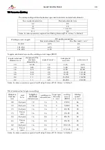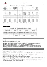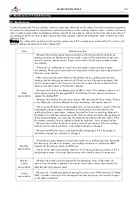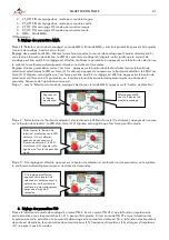
SMART 200 TIG PULSE
26
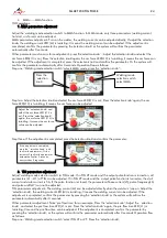
Step two: Adjust the‘selection knob’and select the output pulse LED (L11 is on); press the ‘selection knob’ again, the
pulse LED (L11) is twinkling; It means the output pulse function can be turned on or turned off.
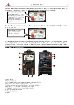
Step three: Press the ‘selection knob’ again, the output pulsed conditions transform by “ON” into “OFF” or transform
by “OFF” into “ON”.
The operation panel will return to original condition; welding current LED (L4) is on. If the welding mode is TIG and
the output pulse function is turned on, the pulse pilot light (L11) is on. If the output pulse function is turned off, the
pulse pilot light (L11) is off. In MMA mode, the pulse pilot light (L11) is off. All preset parameters with hold function.
3.2. Layout for the front panel
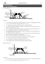
1.Front panel
2.Operation panel
3.Shield gas connector is connected to the gas input pipe of torch.
4.Connector the welder’s negative polarity output.
5.Aero socket is connected to torch switch control wire (8 leads).
6.Connector
The welder’s positive polarity output.
7. Shield gas input joint, to connected to gas cylinder.
8. Power source switch On/Off
9. Power source input
10. Fan
Adjust the
‘
selection knob
’
and
select the pulse LED (L11 is on);
Press the ‘selection knob’ again,
the pulse LED (L11) is twinkling;
It means the output pulse
function can be turned on or
turned off.
Press the
‘selection knob’
again,
the output pulse
function is turned off.
1
2
3
4
5
6
7
8
9
10

