


Pub. 42004-392G
M
ODEL
LE200-RM
R
ACK
-M
OUNT
P
AGE
/P
ARTY
®
L
INE
E
XTENDER
P
AGE
29 of 56
e:\standard ioms - current release\42004 instr. manuals\42004-392g.doc
09/14
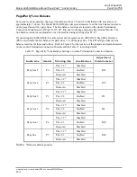
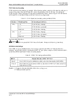
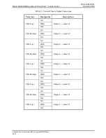
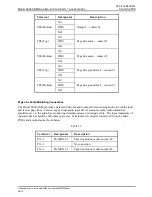
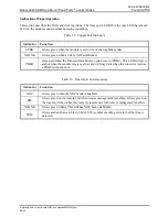
When using GAI-Tronics 60029 Series system cable, follow the wiring color code as shown in Table 27
below:
Table 27. Color Codes for GAI-Tronics 60029 Series System Cable
Terminal
Designator
GTC System
Cable Color Code
Description
P5-1/P8-1 PAGE
-
L1
Red/blue
Page line audio
P5-2/P8-2 PAGE
-
L2
Blue/red
P5-3/P8-3
PARTY 1 - L1
Red
Party line 1 audio
P5-4/P8-4
PARTY 1 - L2
Tan/red
P5-5/P8-5
PARTY 2 - L1
Violet
Party line 2 audio
P5-6/P8-6
PARTY 2 - L2
Tan/violet
P5-7/P8-7
PARTY 3 - L1
Blue
Party line 3 audio
P5-8/P8-8
PARTY 3 - L2
Tan/blue
P5-9/P8-9
PARTY 4 - L1
Brown
Party line 4 audio
P5-10/P8-10
PARTY 4 - L2
Tan/brown
P5-11/P8-11
PARTY 5 - L1
Yellow
Party line 5 audio
P5-12/P8-12
PARTY 5 - L2
Tan/yellow
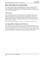
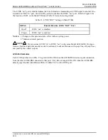
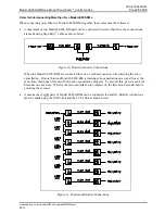
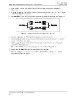
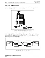
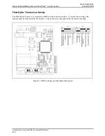
T1/E1 Data Connections
A two-pair cable is required for the T1/E1 data line connection between Line Extenders. Connect the
T1/E1 data cable to P19 on the Main PCBA. The transmit (TX) and receive (RX) pairs between Line
Extenders must be wired in a cross-over fashion such that the TX terminals of Line Extender #1 are
connected to the RX terminals of Line Extender #2 and vice-versa. Each data cable connection point is
labeled next to the terminal block P19 as shown below.
Figure 14. Data Line Terminals