


Pub. 42004-392G
M
ODEL
LE200-RM
R
ACK
-M
OUNT
P
AGE
/P
ARTY
®
L
INE
E
XTENDER
P
AGE
19 of 56
e:\standard ioms - current release\42004 instr. manuals\42004-392g.doc
09/14
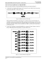
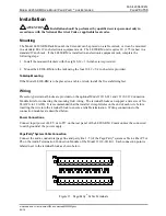
Configuring the Data Links
The T1/E1 and LVDS data link parameters between Line Extenders must be configured using multiple
DIP switch settings on the Main PCBA. The following sections describe each parameter and the switch
settings.
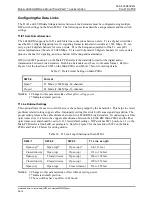
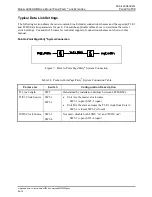
T1/E1 Data Format Selection
The LE200-RM supports both T1 and E1data line connections between units. T1 is a digital circuit that
uses the DS-1 (Digital Signaling level 1) signaling format to transmit voice/data at 1.544 Mbps. T1 can
carry up to 24 digital channels for voice or data. E1 is the European equivalent of the T1, except E1
carries information at the rate of 2.048 Mbps. E1 is used to transmit 30 digital channels for voice or data
plus one channel for signaling, and one channel for framing and maintenance.
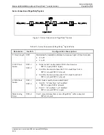
DIP switch SW5 position 8 on the Main PCBA selects the data link format for the digital audio
transmission between Line Extenders. Both Line Extenders must be set to the same format. Refer to
Figure 6 for the location of SW5 on the Main PCBA and Table 17 below for setting details.
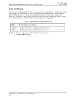
Table 17. Data Format Setting on Main PCBA
SW5-8 Format
Open*
T1 Mode (1.544 Mbps, 24-channel)
Closed
E1 Mode (2.048 Mbps, 32-channel)
N
OTES
:
1. Changes to this parameter take effect
after cycling power
.
2.
*Indicates
default
position.
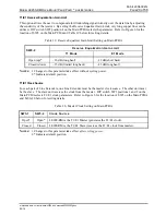
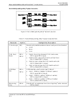
T1 Line Build-out Settings
This option allows the user to control the wave shape being output by the transmitter. This helps to correct
problems related to long copper cables. Improperly setting this switch will cause signal degradation. The
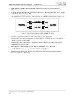
proper setting refers to the cable distance between two LE200-RM Line Extenders. If connecting to a fiber
optic transceiver, it refers to the copper cable distance between the LE300-RM Main PCBA and the fiber
optic transceiver and should be set to 0–133 feet (default setting). DIP switches SW2 positions 1–3 on the
Main PCBA selects line-build out parameters. Refer to Figure 6 for the location of SW2 on the Main
PCBA and Table 18 below for setting details.
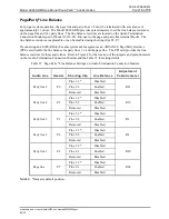
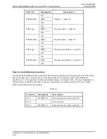
Table 18. T1 Line Length Setting on Main PCBA
SW2-1 SW2-2 SW2-3 T1
Line
Length
Open (up)*
Open (up)*
Open (up)*
0 to 133 feet
Closed (down)
Open (up)
Open (up)
133 to 266 feet
Open (up)
Closed (down)
Open (up)
266 to 399 feet
Closed (down)
Closed (down)
Open (up)
399 to 533 feet
Open (up)
Open (up)
Closed (down)
533 to 655 feet
N
OTES
:
1. Changes to this parameter take effect without cycling power.
2.
*Indicates
default
position.
3. These switches have no effect in E1 mode.