


Pub. 42004-392G
M
ODEL
LE200-RM
R
ACK
-M
OUNT
P
AGE
/P
ARTY
®
L
INE
E
XTENDER
P
AGE
28 of 56
e:\standard ioms - current release\42004 instr. manuals\42004-392g.doc
09/14
Installation
ATTENTION
Installation should be performed by qualified service personnel only in
accordance with the National Electrical Code or applicable local codes.
Mounting
The Model LE200-RM Rack-Mount Line Extender can be placed on a table or desk, or it can be mounted
in a standard EIA 19-inch electronic equipment rack. The LE200-RM unit requires 1U (1.75 inches) in a
standard 19-inch rack. If the LE200-RM is installed in an electronic equipment rack, complete the
following steps:
1.
Install the mounted brackets with the eight 8-32
3/8-inch screws provided.
2.
Mount the LE200-RM into the rack using the four 10-32
3/4-inch screws provided.
Tabletop Mounting
If the Model LE200-RM is to be placed on a table or desk, install the five stabilizing feet.
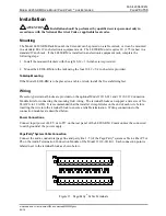
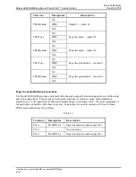
Wiring
Pressure-type terminal blocks are provided on the optional Model 12118-011 and 12118-012 Connection
Module Kits for connecting the incoming field wiring. The terminal blocks can support a wire size of No.
24 AWG to 12 AWG. It is recommended that the installer crimp ferrules on the end of each wire before
inserting the wire into the terminal block to ensure a reliable termination. Wiring connections to the
connection modules are described below.
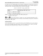
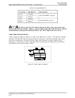
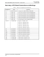
Power Connections
Connect input power of 48 V dc to P17 on the rear panel of the LE200-RM. Common must be connected
to earth ground at the power supply.
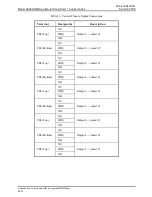
Page/Party
®
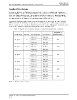
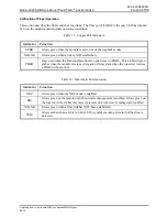
System Cable Connection
Connect the audio conductors (page line and party line 1–5) of the Page/Party
®
system cable to either P5 or
P8 on the Audio Termination Connection Module of the Model 12118-011 Kit. Each connection point is
labeled next to the terminal block as shown below.
Figure 13
.
Page/Party
®
Cable Terminals