3
CONTENTS
CONTENTS
CONTENTS
CONTENTS
CONTENTS
1 INTRODUCTION
1 INTRODUCTION
1 INTRODUCTION
1 INTRODUCTION
1 INTRODUCTION
2 OPERA
2 OPERA
2 OPERA
2 OPERA
2 OPERATOR CONTROLS
TOR CONTROLS
TOR CONTROLS
TOR CONTROLS
TOR CONTROLS
3 TECHNICAL INFORMA
3 TECHNICAL INFORMA
3 TECHNICAL INFORMA
3 TECHNICAL INFORMA
3 TECHNICAL INFORMATION
TION
TION
TION
TION
5 COMMISSIONING
5 COMMISSIONING
5 COMMISSIONING
5 COMMISSIONING
5 COMMISSIONING
7 F
7 F
7 F
7 F
7 FAUL
AUL
AUL
AUL
AULT FINDING
T FINDING
T FINDING
T FINDING
T FINDING
CONTENTS
CONTENTS
CONTENTS
CONTENTS
CONTENTS
Impor
Impor
Impor
Impor
Important Information
tant Information
tant Information
tant Information
tant Information -----------------------------------------
-----------------------------------------
-----------------------------------------
-----------------------------------------
----------------------------------------- 4
Section 1 Intr
Section 1 Intr
Section 1 Intr
Section 1 Intr
Section 1 Introduction
oduction
oduction
oduction
oduction
1-1 Introduction ---------------------------------------------- 5
1-2 System Layout ------------------------------------------- 8
1-3 Parts Supplied------------------------------------------- 11
1-4 The Electrastream System ------------------------------- 12
1-5 Tri Core Heater Operation -------------------------------- 13
Section 2 Operator Contr
Section 2 Operator Contr
Section 2 Operator Contr
Section 2 Operator Contr
Section 2 Operator Controls
ols
ols
ols
ols
2-1 System Control ------------------------------------------ 14
2-2 Electrastream Control Unit ------------------------------- 16
2-3 Shut Off Valves ------------------------------------------ 20
2-4 Temperature & Pressure Relief Discharge ---------------- 22
2-5 Thermostatic Mixing Valve ------------------------------ 22
2-6 Servicing ------------------------------------------------ 22
Section 3 T
Section 3 T
Section 3 T
Section 3 T
Section 3 Technical Information
echnical Information
echnical Information
echnical Information
echnical Information
3-1 Specifications ------------------------------------------- 23
3-2 Dimensions --------------------------------------------- 25
3-3 Wiring --------------------------------------------------- 29
Section 4 Installation
Section 4 Installation
Section 4 Installation
Section 4 Installation
Section 4 Installation
4-1 Building Control ----------------------------------------- 31
4-2 Electrical ------------------------------------------------ 31
4-3 Hot Water System --------------------------------------- 33
4-4 Heating System ----------------------------------------- 37
4-5 Expansion Discharge ------------------------------------ 40
4-6 System Pressure ---------------------------------------- 43
4-7 Electrastream Connections - ---------------------------- 44
Section 5 Commissioning
Section 5 Commissioning
Section 5 Commissioning
Section 5 Commissioning
Section 5 Commissioning
5-1 Commissioning ----------------------------------------- 47
Section 6 Servicing
Section 6 Servicing
Section 6 Servicing
Section 6 Servicing
Section 6 Servicing
6-1 Routine Service ----------------------------------------- 50
Section 7 Fault Finding
Section 7 Fault Finding
Section 7 Fault Finding
Section 7 Fault Finding
Section 7 Fault Finding
7-1 Fault Finding -------------------------------------------- 52
Health & Safety
Health & Safety
Health & Safety
Health & Safety
Health & Safety ------------------------------
------------------------------
------------------------------
------------------------------
------------------------------ Inside Front Cover
6 SERVICING
6 SERVICING
6 SERVICING
6 SERVICING
6 SERVICING
4 INST
4 INST
4 INST
4 INST
4 INSTALLA
ALLA
ALLA
ALLA
ALLATION
TION
TION
TION
TION
IMPORTANT
BEFORE STARTING THE INSTALLATION OF THE ELECTRASTREAM CHECK ALL COMPONENTS HAVE
BEEN DELIVERED AND ARE IN SATISFACTORY CONDITION - Refer to 1-3 .
HEAL
HEAL
HEAL
HEAL
HEALTH & SAFETY
TH & SAFETY
TH & SAFETY
TH & SAFETY
TH & SAFETY
37
Fig. 4-4a Schematic of Typical Heating System
4-4
Heating System
INST
INST
INST
INST
INSTALLA
ALLA
ALLA
ALLA
ALLATION 4
TION 4
TION 4
TION 4
TION 4
4-4.1 Notes on Heating System
1. The total output from the Electrastream for hot water and heating is 9 kW @ 240V
(30,000 Btu). The radiators should be sized to suit.
2. The schematic system shows a kick space fan assisted heater, these are efficient
space saving units, ideal for small dwellings.
4-4.2 Pressure Gauge
The pressure gauge is provided to indicate the heating system pressure.
When the system is full with cold water and all radiators are full, on and bled/vented, the
gauge will show the cold fill pressure.
Set the red pointer to the cold fill pressure. If the system pressure, indicated by the black
pointer, falls below the cold fill pressure, it means that the system requires topping up.
4-4.3 Pump
Electrastream is supplied with a standard 3 speed central heating circulating pump and
isolating valves. This should be fitted in the flow from the indirect cylinder before the
bypass valve.
Normally the pump will be set at speed 2 (II).
The pump is wired so that it is ON when the heating control system is set for heating ON
and the room thermostat is set higher than the ambient temperature - see wiring diagrams
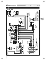
figs. 3-3a and 3-3b.
4-4.4 Heating PRV
The pressure relief valve (PRV) is provided to vent excess pressure from the system. The
valve will open when the pressure exceeds 3 Bar ± 10%.
The valve can be manually opened by turning the red knob clockwise, to close the valve
continue turning clockwise until it clicks.
✓
SUPPLIED
Fig. 4-4b Pressure Gauge
Fig. 4-4c Pump Speed
SINGLE COIL CYLINDER SHOWN
TWIN COIL - CONNECT TO TOP COIL
44444
Содержание Electrastream
Страница 55: ...55 ...

