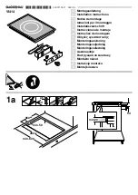
Schaltpult einbauen (Bild 3 + 4)
Hinweis:
Das Gerät nur zusammen mit dem dazugehörigen
Schaltpult einbauen.
1.
Verpackung der Bedienknebel entfernen und die Schutzfolie
hinter den Leuchtringen abziehen.
2.
Halteblech von hinten gegen die Frontblende halten. Bedienk-
nebel von vorne in die Bohrungen stecken, von hinten mit den
Muttern festschrauben. Auf korrekte Zuordnung der Bedienk-
nebel achten (siehe Bild).
3.
Schaltpult mit den beiliegenden Muttern an dem Halteblech
festschrauben.
Gerät einbauen
Hinweis:
Zum Einbauen des Kochfeldes Schutzhandschuhe ver-
wenden. Die nicht sichtbaren Flächen können scharfe Kanten
aufweisen.
1.
Steckerschutz an der Unterseite des Kochfeldes abnehmen,
Kabel des Schaltpults laut Skizze mit Buchse verbinden. Ste-
cker müssen einrasten. Erdungskabel festschrauben und
Schaltpultkabel in der Zugentlastung fixieren. Steckerschutz
wieder aufsetzen
(Bild 5)
.
2.
Gerät gleichmäßig in den Ausschnitt einsetzen. Von oben fest
in den Ausschnitt drücken
(Bild 6a)
.
Hinweis:
Das Gerät muss fest im Ausschnitt sitzen und darf
sich nicht verschieben (z. B. bei der Reinigung). Bei Aus-
schnittsbreite an der oberen Toleranzgrenze wenn nötig Leis-
ten seitlich im Ausschnitt befestigen.
3.
Gerät ans Netz anschließen und Funktion prüfen. Lässt sich
das Gerät nicht einschalten, ist das Verbindungskabel zwi-
schen Schaltpult und Gerät nicht eingesteckt. Den korrekten
Sitz des Verbindungskabels prüfen!
Hinweis:
Je nach Anschlussart muss eventuell die Anordnung
der vom Werk gelieferten Klemmen verändert werden.
– Spannung siehe Typenschild.
– Nur nach Anschlussplan anschließen.
– Das Erdnungskabel (Farbe grün und gelb) muss als erstes
angeschlossen und als letztes abgeklemmt werden. Außer-
dem muss dieses Kabel länger sein als alle anderen Kabel,
damit beim eventuellen Bewegen des Kochfeldes alle ande-
ren Kabel zuerst vom Netz getrennt werden, bevor dieses
getrennt wird
(Abb. 7)
.
– Leitung bei Einbau nicht einklemmen und nicht über scharfe
Kanten führen.
– Sie dürfen das Kochfeld und die Arbeitsplatte nicht mit Sili-
kon verfugen. Das Kochfeld ist zu diesem Zweck bereits mit
einer Dichtung ausgestattet.
4.
Nur bei flächenbündigem Einbau (Bild 6b): Vor dem Verfu-
gen unbedingt Funktionstest durchführen!
Umlaufenden
Spalt mit einem geeigneten, temperaturbeständigen Sili-
konkleber verfugen (z. B. OTTOSEAL
®
S 70). Dichtfuge mit
dem vom Hersteller empfohlenen Glättmittel glätten. Verarbei-
tungshinweise des Silikonklebers beachten. Gerät erst nach
vollständigem Austrocknen des Silikonklebers in Betrieb neh-
men (mindestens 24 Stunden, je nach Raumtemperatur).
Achtung!
Ungeeigneter Silikonkleber führt bei Naturstein-Arbeitsplatten
zu dauerhaften Verfärbungen.
Gerät ausbauen
Gerät stromlos machen. Bei flächenbündig eingebauten Gerä-
ten die Silikonfuge entfernen. Gerät von unten herausdrücken.
Achtung!
Geräteschaden! Gerät nicht von oben heraushebeln.
en
Ú
Installation instructions
Important notes
Safety in use is only guaranteed if the technical installation of
the hob has been carried out correctly and in accordance with
the installation instructions. The installation technician shall be
liable for any damage caused as a result of incorrect installation.
Only an authorised technician is able to connect the appliance.
The guidelines set out by the local electricity provider must be
observed.
This is a class I appliance and should only be used with an
earthed connection.
Using this appliance without an earth connection or after it has
been incorrectly installed may, under very rare circumstances,
cause serious harm.
The manufacturer accepts no responsibility for any malfunction
or damage caused by incorrect electrical installation.
The appliance must be connected to a fixed installation and the
means of disconnecting it from the fixed installation must be
included according to the installation instructions.
The inlet hose must be positioned so that it does not touch any
of the hot parts of the hob or oven.
Induction hobs may only be installed over ovens with the same
brand of forced-air ventilation. Refrigerators, unventilated ovens,
and washing machines may not be installed beneath the hob.
Any change to the appliance's interior, including changing the
power cable, must be performed by the Technical Assistance
Service.
Preparing kitchen units
The worktop must be flat and horizontal. Produce all
apertures on furniture and the worktop before inserting
appliances. Remove any shavings, as these can affect the
operation of electrical components. When the cutting has
been completed, the unit's stability should be checked again.
■
Fit a heat-resistant seal on cut surfaces to prevent swelling
caused by moisture.
■
Kitchen units must be temperature-resistant up to 90 °C.
■
The gap between the aperture and the side wall must be at
least 40 mm.
It is not recommended that the cooktop be placed between two
side walls but, if this is the case, a gap of at least 200 mm
should also be left on one side.
■
Pay attention to a minimum gap of 10 mm from the underside
of the appliance to kitchen units.
The worktop must be reinforced if it is less than 20 mm thick
when installed overlapping or less than 30 mm when installed
flush. Otherwise, it is not stable enough. Reinforcement material
used must be resistant to heat and moisture.
Notes
■
The worktop where the hob is installed should be able to
support a weight of approximately 60 kg.
■
The hob levelling should only be checked after it is installed in
the gap for the built-in unit.
Flush installation (Figure 1b)
Flush installation in a worktop is possible.
The appliance can be installed in the following temperature-
resistant and waterproof worktops:
■
Stone worktops
■
Worktops made of plastics (e.g. Corian
®
)
■
Solid wood worktops: Only by arrangement the with worktop
manufacturer (seal recess edges)
■
For other materials, coordinate with the worktop manufacturer
with regard to use.
Installation in laminated wood worktops is not possible.
Note:
All recessing work on the worktop must be performed in a
specialist workshop on the basis of the installation sketch. The
recess must be produced neatly and precisely because the cut
edge is visible on the surface. Clean and degrease the recess
edges with a suitable cleaning agent (observe the silicone
manufacturer's processing notes).
Combination of several Vario appliances (fig. 1c)
The connecting strip VA 420 000/001/010/011 is required to
combine several Vario appliances. This is available separately
as an optional accessory. When creating the cut-out, allow
sufficient space for the connecting strip between the appliances
(see installation instructions VA 420 000/001/010/011).
Appliances can be also be installed in individual cut-outs by
leaving a space between the cut-outs with a minimum width of
50 mm.
To enable combination of appliances with and without an
appliance cover, dimension differences can be balanced out by
the extension VA 450 110/-400/-600/-800/-900 (depending on
appliance width).
Ventilation (Figure 1d)
In view of ventilation of the cooktop, an aperture with a width of
550 mm and a height of 45 mm must be provided in the top
area of the kitchen unit's rear panel.
The space between the unit's rear panel and the wall must be at
least 20 mm.
Содержание VI 461
Страница 2: ...PLQ PLQ E PLQ U F 9 9 G PLQ PLQ PLQ...
Страница 3: ...D PLQ PD PLQ PLQ PLQ PLQ PLQ E PLQ PLQ PLQ PLQ PD...
Страница 4: ...D E...
Страница 24: ......


