7
8/18 REV. 2/23
GB808HVB
-
100 INSTALLATION TOOL
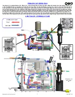
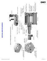
PRINCIPLE OF OPERATION
Incoming air is regulated between 90
-
100psi. (6.2
-
6.9 bar) through the air filter / regulator. When the actuator lever assembly is depressed
on the installation tool, pressurized air inside the four
-
way valve is released allowing a plunger to unseat a valve ball allowing the air
to be redirected to the rear of the booster starting the cycle. As the air piston in the booster begins to move forward the air in the front
side is being exhausted out of the muffler and simultaneously forcing hydraulic oil up and into the front side of the head cylinder assembly,
causing the head piston to move to the rear of the head cylinder assembly. The internal components of the attached nose assembly
are also moving with the head piston to start the fastener installation. When the fastener installation is completed, the actuator lever
assembly is released. Air pressure is then built up inside of the four
-
way valve re
-
seating the valve ball that in return directs the air to
the front side of the booster and to the rear of the head cylinder reversing the sequence while vacuuming the spent pintail into the collection bottle.
RETURN
PULL
EXHAUST
HYDRAULIC FLOW
“
PULL
”
“
RETURN
”
RETURN
PULL
4 WAY VALVE / HYDRAULIC FLOW
FOUR WAY VALVE
Images may not
reflect actual
tool
Содержание GB808HVB-100
Страница 14: ...14 8 18 REV 2 23 GB808HVB 100 INSTALLATION TOOL OVERHAUL BOOSTER ASSEMBLY...
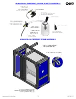
Страница 17: ...17 8 18 REV 2 23 GB808HVB 100 INSTALLATION TOOL GB808HVB 100 POWERUNIT GB808HVB 100 POWERUNIT...
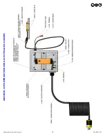
Страница 19: ...19 8 18 REV 2 23 GB808HVB 100 INSTALLATION TOOL GB808HVB 100 POWERUNIT SENSOR ELECTRICAL ENCLOSURE...
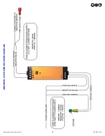
Страница 20: ...20 8 18 REV 2 23 GB808HVB 100 INSTALLATION TOOL GB808HVB 100 POWERUNIT WIRE DIAGRAM...
Страница 23: ...23 8 18 REV 2 23 GB808HVB 100 INSTALLATION TOOL This page intentionally left blank...


