


8
8/18 REV. 2/23
GB808HVB
-
100 INSTALLATION TOOL
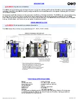
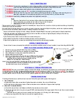
HOW TO SET
-
UP THE GB808HVB
-
100 POWER UNIT
WARNING:
Only qualified and trained operators shall install, adjust or use the assembly power tool for non
-
threaded
mechanical fasteners.
WARNING:
Operator
MUST
read and understand all warnings and cautions.
WARNING:
It is required that eye protection, hearing protection and foot protection be worn during operation.
WARNING:
The users or the user
’
s employer must assess specific risks that could be present as a result after each use
based on their application.
●
Ensure there is adequate clearance for tool and operator's hands before proceeding. Keep fingers clear of any
moving parts. Keep fingers clear from fasteners and installed materials. Severe personal injury may result.
●
Verify that hydraulic hose fittings and couplings, air and electrical connections are secure.
●
Verify
the air lines and/or hydraulic hoses are not a trip hazard.
●
Ensure that there are no electrical cables, gas pipes, etc., which can cause a hazard if damaged by the tool.
●
Ensure Do not use as a hammer to force fasteners into holes or otherwise abuse tool.
WARNING:
Do not actuate fastener in the air. Personal injury from fastener ejecting may occur.
WARNING:
Do not use in explosive atmosphere.
WARNING:
Ensure air hose is securely connected to avoid possible hose whipping.
WARNING:
Always disconnect air supply when tool is not in use to prevent accidental start
-
up.
CAUTION:
Do not use beyond the design intent.
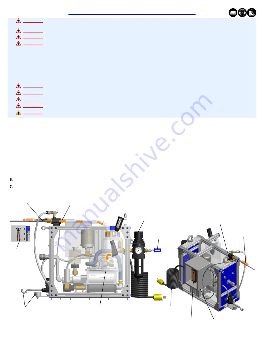
Images may not reflect actual tool
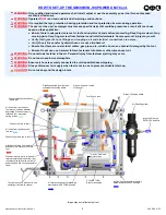
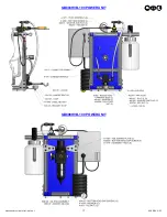
The powerunit is shipped with a plastic plug in the air inlet connector. The connector has a 1/4
-
18 NPT female pipe thread to accept
end
-
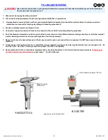
user air hose fitting. The tool comes with oil and is ready to use.
1. Remove red plastic plug in the air inlet connector and install male air fitting with 1/4
-
18 NPT. (Not sold with powerunit).
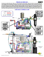
2. Connect powerunit to power unit by attaching hydraulic hose, air line and vacuum line.
3. Connect air supply to powerunit using
1/2”
air line min. (90
-
100 P.S.I.) (6.2
-
6.9 bar) required.
Note: Gage Bilt does NOT recommend using a pneumatic lubricator or adding oil to the air inlet on our tools or powerunit.
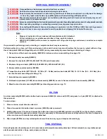
4.
Connect connection wire to inductive sensor. Plug power cord into 110V outlet. (Power supply in electrical enclosure and inductive
sensor have lights that turn green when power supplied).
5. Cycle the powerunit (with tool attached) several times. Re
-
check the hydraulic oil reservoir level with the powerunit in the RETURN position.
Check for leaks.
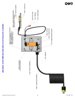
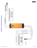
See installation tool manual for complete set up installation instructions.
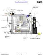
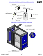
Tool rests on hook when
not in use, shutting off air
flow to vacuum
Pintails extracted from tool and
collected in collection bottle
Connect pintail evacuation
tube to tool
PNP Output
Air Filter/Regulator
Incoming Plant Air
90 PSI (6.2 bar) Min.
Pintail Collection bottle
110V Power Cord
Power Supply
Inductive Sensor
Connection Wire
Electrical Enclosure
Содержание GB808HVB-100
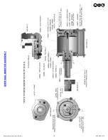
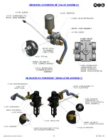
Страница 14: ...14 8 18 REV 2 23 GB808HVB 100 INSTALLATION TOOL OVERHAUL BOOSTER ASSEMBLY...
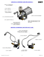
Страница 17: ...17 8 18 REV 2 23 GB808HVB 100 INSTALLATION TOOL GB808HVB 100 POWERUNIT GB808HVB 100 POWERUNIT...
Страница 19: ...19 8 18 REV 2 23 GB808HVB 100 INSTALLATION TOOL GB808HVB 100 POWERUNIT SENSOR ELECTRICAL ENCLOSURE...
Страница 20: ...20 8 18 REV 2 23 GB808HVB 100 INSTALLATION TOOL GB808HVB 100 POWERUNIT WIRE DIAGRAM...
Страница 23: ...23 8 18 REV 2 23 GB808HVB 100 INSTALLATION TOOL This page intentionally left blank...


