9
SL DC2 GATE MOTOR
INSTALLATION AND SET UP
INSTRUCTIONS
Mounting the Gate Motor / Limit Switch Brackets
:
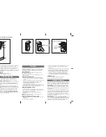
The limit switch brackets are mounted at either end of the gear rack to set the open and close positions of
the gate.
Put the gate motor into ‘manual mode’. Manually slide the gate into the fully closed position and then
open the gate 15 —25mm. Attach one limit switch bracket onto the rack so the end of the bracket just
touches the limit switch spring. Manually slide the gate at the fully open position and then close the gate
15 —25mm. Attach one limit switch bracket onto the rack so the end of the bracket just touches the limit
switch spring. In these positions, when the gate motor is operating, the limit switch brackets should push
against the limit switch spring to click the limit switch off (an audible sound can be heard when the
switching occurs).
Put the gate motor into ‘automatic mode’ and activate the gate motor to open and close the gate several
times to ensure the limit switch brackets are correctly positioned. Adjust the bracket position as required.
The gate should stop in the open and closed positions
before
making contact any end stops Ensure the
brackets and bracket screws do not hit, rub or contact any part of the motor cover or motor body.
Limit Switch Bracket
Limit Switch spring
Gear Rack
Limit Switch
Bracket
Gear Rack
POWER WIRE ENTRY
Power Wire external
entry
Power Wire Internal entry.
Drill a hole in the plastic insect
shield for the cable
© 2012 G Force Automatic Gates All Rights Reserved


