


3+3+. N\ejfi NlYd\el
K^mkb\ ngbml9
bIvd
Ivd IvZd
Ivdd
Þ
mhkjn^ l^glhk
bI
I
Þ
_hk\^ l^glhk
Gfi^kbZe ngbml9
cY]k
’
@?D>5 7?A46 766C
(
Þ
mhkjn^ l^glhk
cY‘e
’
@?D>5 7?A46 :>496B
(
Þ
mhkjn^ l^glhk
fq‘e
’
?D>46$7?A46 :>496B
(
Þ
mhkjn^ l^glhk
cY]
’
@?D>5 7?A46
(
Þ
_hk\^ l^glhk
Qb‘g-Ibg]
*.,0/T
4
Pe‘k
Ivd
4
N‘^e+F‘e[
(,*.-Q
Sgbm
L{f
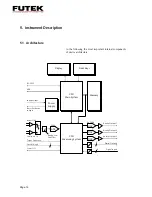
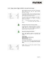
The
IBT
100 instrument is parameterized in the ’
Sensor
’
menu using a connected torque or force sensor.
Assignments between the output voltage/frequency and
applied rated torque or rated force of a sensor are
configured in this menu.
When connecting a dual-range sensor, it is possible to
define two nominal ranges of use (1st and 2nd range).
The number of pulses of speed sensors as well as other
settings for the display in measurement mode (number of
decimal places, additional measurement parameters,
etc.) are also specified in this menu. The various setting
options are shown and explained in detail in the following
section:
In ’
Sign.Kind
’, a choice can be made between ’
Bridge
’ ,
’
+/-10V
’ and ’
Freq.
’.
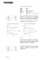
In this menu
item
,
the
user
chooses
a
passive
or active
sensor. An active sensor with voltage output (0…
±
10V) is
selected with ’
+/-10V
’. Sensors with a torque-equivalent
frequency output are selected with ’
Freq.
’. A passive
sensor contains a strain gage bridge without its own
measured value amplifier. This is selected with ’
Bridge
’.
Depending on which function is activated, the diagram
and the subsequent setting options change to the present
display.
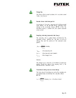
A choice can be made between the following units for the
signal type in ’
Unit
’:
It is possible to differentiate between a torque and a force
sensor by the units. The factors for calculating the
mechanical power are automatically taken into account.
Page 26