


H\Xjli\[ mXcl\ Zfem\ij‘fe ]fi gXjj‘m\ j\ejfij
C\e\iXk‘e^ X kXZ_f j‘^eXc ]ifd k_\ jg\\[
?XYc\ j_‘\c[) cXp‘e^ k_\ d\Xjli\d\ek ZXYc\
Aok\ieXc Zfekifc j‘^eXcj
BZg‘^k h_ bg]n\mbhg hg ma^ f^Zlnk^f^gm
lb‘gZe Zl Z k^lnem h_ ^e^\mkhfZ‘g^mb\ _b^e]l
C__^\mbo^ bg]n\mbo^ lnk_Z\^l Zk^ k^]n\^] [r
[b_beZk eZrbg‘
K^Zl- \Z[e^ \Z[e^ ]n\m
K^Zl- \Z[e^ \Z[e^ ]n\m
þ
!
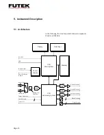
If the torque signal is to be used for control or regulation
purposes, this can be carried out with the analog outputs
of the Supply and Evaluation Instrument,
IBT
100. This
can be particularly advantageous with a passive sensor
(mV/V signals) (works as a measured value amplifier).
The speed recorded and measured by the
IBT
100
instrument can be converted into a voltage parameter
with an analog output. This output voltage is proportional
to the speed/angle of rotation (tacho signal).
Use shielded cables if possible. Do not lay them
parallel to power lines or control lines.
Do not lay them close to strong electromagnetic fields,
e.g. transformers, welders, magnetic switches,
motors, etc.
If this is unavoidable, lay the measurement cable in
a grounded, armored steel tube.
Avoid excess cable lengths. If this is not possible,
do not wind excess lengths as a closed cable loop in
order to keep induction surfaces as small as possible!
Digital signal states can be generated via the digital input
and output signals of the Supply and Evaluation
Instrument,
IBT
100 (e.g. if limit values are exceeded). It
is also possible to detect digital input signals of a PLC via
the serial interface of the
IBT
100 instrument.
Page 16