background image


System Components 

Carbon Filter Installation Instructions 

WATER PRESSURE: A minimum of 20 pounds of water pressure is required for regeneration valve to operate effectively. 

ELECTRICAL FACILITIES: An uninterrupted alternating current (A/C) supply is required. Note: Other voltages are avail-
able. Please make sure your voltage supply is compatible with your unit before installation. 

EXISTING PLUMBING: Condition of existing plumbing should be free from lime and iron buildup. Piping that is built up 
heavily with lime and/or iron should be replaced.  

LOCATION OF FILTER AND DRAIN: The filter should be located close to a drain to prevent air breaks and back flow.  

BY-PASS VALVES: Always provide for the installation of a by-pass valve if unit is not equipped with one. 

CAUTION: Water pressure is not to exceed 125 psi, water temperature is not to exceed 110°F, and the unit can-
not be subjected to freezing conditions. 

1.  Place the filter tank where you want to install the unit making sure the unit is level and on a 

firm base. 

2.  During cold weather, the installer should warm the valve to room temperature before operat-

ing. 

3.  All plumbing should be done in accordance with local plumbing codes. The pipe size for 

residential drain line should be a minimum of 1/2". Backwash flow rates in excess of 7 

gpm or length in excess of 20’ require 3/4" drain line. Commercial drain lines should be 

the same size as the drain line flow control. 

4.  The inlet on the bypass valve is indicated by an arrow that will point toward the valve.  

The outlet will be indicated by an arrow pointing away from the valve. 

5.  Lubricate the distributor o-ring seal and tank "o" ring seal. Place the main control valve on 

tank. Note: Only use silicone lubricant. 

6.  Solder joints near the drain must be done prior to connecting the Drain Line Flow Control 

fitting (DLFC). Leave at least 6" between the DLFC and solder joints when soldering pipes 

that are connected on the DLFC. Failure to do this could cause interior damage to the 

DLFC. 

7.  Teflon tape is the only sealant to be used on the drain fitting.  
8.  On units with a by-pass, place in by-pass position. Turn on the main water supply. Open a 

cold  water tap nearby and let run a few minutes or until the system is free from foreign ma-

terial (usually solder) that may have resulted from the installation. Once clean, close the wa-

ter tap. 

9.  Slowly place the by-pass in service position and let water flow into the media tank until the 

water flow stops. 

10. Plug unit into an electrical outlet. Note: All electrical connections must be connected accord-

ing to local codes. (Be certain the outlet is uninterrupted). 


Installation, Operation and Maintenance Manual 

Oxi-Gen Oxi-2P,3P,4P, 5P & 6P System 

Содержание Oxi-Gen 150-OXi-2P

Страница 1: ...on Sulfur and Manganese Eradication System Oxi Gen 150 OXi 2P Oxi Gen 150 OXi 3P Oxi Gen 150 OXi 4P Oxi Gen 150 OXi 5P Oxi Gen 150 OXi 6P US Water Systems Inc 1209 Country Club Road Indianapolis IN 46...

Страница 2: ...and Valve Installation 8 Carbon Filter Installation Instructions 9 Carbon Filter Valve Features 10 Carbon Filter Valve Features and Programming 12 Carbon Filter Valve Programming 13 Carbon Filter Sta...

Страница 3: ...er of bathrooms 1 Bathroom 5 GPM 2 Bathrooms 8 GPM 3 Bathrooms 10 GPM 4 Bathrooms 12 GPM 5 Bathrooms 15 GPM 6 Bathrooms 20 GPM Hydrogen peroxide or H2O2 is a powerful yet versatile oxidant that is bot...

Страница 4: ...e oxidizes the contaminants and the by product is H2O water This is much safer than using chlorine in that chlorine can cause other problems in the water stream such as chloramines and trihalomethanes...

Страница 5: ...to assure the accuracy of the dosage The Stenner Proportional Injection System can be utilized to inject any number of chemicals including chlorine hydrogen peroxide polyphosphate Rid O Rust and many...

Страница 6: ...5 Secure wall mount bracket to wall studs using the included lag bolts or other suitable hardware Hang panel on to wall mount bracket 6 Glue stubbed cut pipe into slip socket After glue is cured hand...

Страница 7: ...4 Slide roof into pump mounting bracket over motor WARNING When pressurizing the system gradually allow water to flow Shocking the meter by over speeding it with high flow rates can damage the interna...

Страница 8: ...stem 1 Remove the tank from carton 2 Verify the riser is still fully engaged in the Vortech plate 3 Place a piece of duct tape over the riser tube so no media enters the riser while filling 4 Make sur...

Страница 9: ...nimum of 1 2 Backwash flow rates in excess of 7 gpm or length in excess of 20 require 3 4 drain line Commercial drain lines should be the same size as the drain line flow control 4 The inlet on the by...

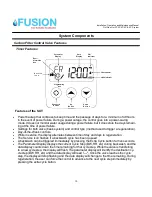
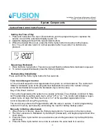
Страница 10: ...by pressing the Extra Cycle button for five seconds The Parameter Display displays the current Cycle Step BW RR etc during backwash and the data display counts down the time remaining for that cycle...

Страница 11: ...d backwash time when the number of days since the last backwash equals the backwash day override value Day of the Week Control This control regenerates the system on a weekly schedule The schedule is...

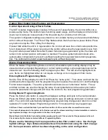
Страница 12: ...or do not appear in filter mode Entering Master Programming Mode Set the Time Of Day display to 12 01 P M Press the extra cycle Then press and hold the Up and Down buttons together until the programmi...

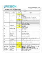
Страница 13: ...2 in Service C Unit Capacity Unit Capacity Grains H Feedwater Hardness Hardness of Inlet Water RS Reserve Selection Percentage Safety Factor rc Fixed Reserve Capacity SF Safety Factor Percentage of t...

Страница 14: ...preferably glass should be full of bubbles immediately after the sample is taken If not the installer will adjust the knob to 50 run the water for 10 15 minutes and check again 4 Continue adjusting th...

Страница 15: ...s an indication that the system is being overfed with H2O2 This occurs because after installation the water will become cleaner and the initial dosage of H2O2 may need to be adjusted to compensate for...

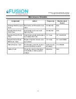
Страница 16: ...ter Open blow down valve and flush the filter 3 6 Months N A Injection Panel Pump Tube Inspect pump tube and replace as needed 2 Tube 1 5 Years 411 UCCP202 Injection Panel Duck Bill Check Valve Replac...

Страница 17: ...17 Flow Schematic Installation Operation and Maintenance Manual Oxi Gen Oxi 2P 3P 4P 5P 6P System...

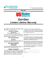
Страница 18: ...ther casualty or if the original serial numbers have been removed Fouling or damage to the resin caused by iron sulfur bacterial iron silt sand tannins or ganics bacteria hot water or chlorine voids t...

Отзывы: