background image

1. INSTALLATION


1-16

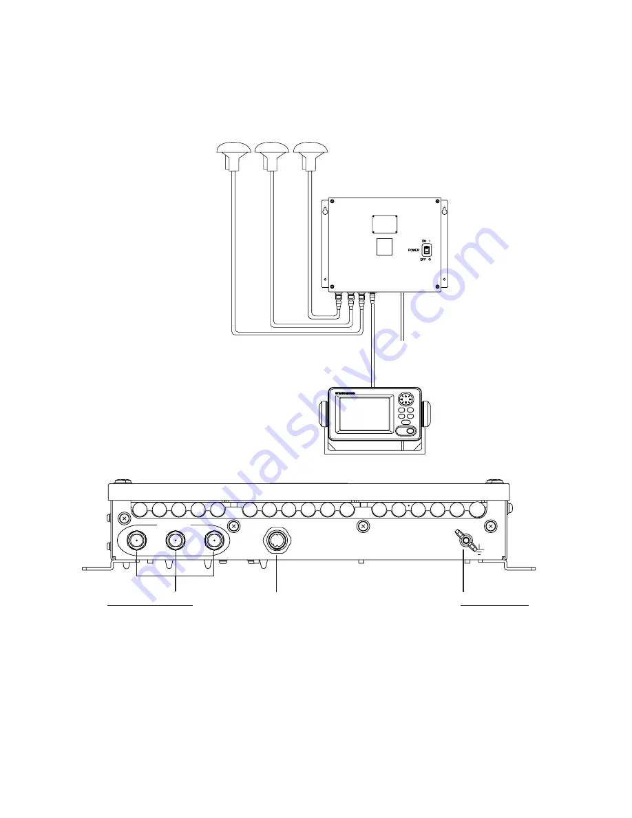
1.4 Wiring 

This section covers general wiring. For further details see the interconnection 
diagram at the back of this manual. 

DISPLAY UNIT
SC-502

PROCESSOR UNIT
SC-501

*

           12-24 VDC

MJ-A7SPF0006-100,
10m

TPPX6-3D2V-15M, 15m
or
TNC-PS-3D-15 (3 pcs.)

DPYC 1.5

ANTENNA UNIT
?????????????????


DISPLAY

3

2

GPS ANT

1

Ground Terminal
Connect IV-2.0 sq 
ground wire to
ship's superstructure.

Cable from display

ANTENNA Terminals
GPS ANT1: No color
GPS ANT2: Yellow line
GPS ANT2: Red line
(using cable TPPX6-3D2V-15M)


Wiring 

Содержание SC-50S

Страница 1: ...abel If the label is missing or damaged contact a FURUNO agent or dealer about replacement WARNING LABEL Name Warning Label 1 Type 86 003 1011 1 Code No 100 236 231 WARNING Do not disassemble or modif...

Страница 2: ...mounting 1 14 1 3 3 Flush mount 1 15 1 4 Wiring 1 16 1 5 Initial Settings 1 19 1 5 1 Confirming satellite status 1 19 1 5 2 Choosing processor unit mounting method 1 20 1 6 Connection of External Equi...

Страница 3: ...g Source for Backup 2 22 3 MAINTENANCE TROUBLESHOOTING 3 1 3 1 Preventive Maintenance 3 1 3 2 Troubleshooting 3 2 3 3 Diagnostics 3 3 3 4 Program Number 3 7 3 5 Clearing Data 3 7 3 6 Replacement of Ba...

Страница 4: ...refully read and follow the operation installation and maintenance procedures set forth in this manual We would appreciate feedback from you the end user about whether we are achieving our purposes Th...

Страница 5: ...ng data 6 ports for Heading or Navigation Data 5 AD 10 IEC 61162 ports 1 AD 10 port External DPGS Beacon Receiver Processor Unit SC 501 Analog roll Analog pitch Log Heading alarm Contact Category of U...

Страница 6: ...2203 004 380 660 1 For display unit Tapping screw 5X20 4 pcs Spare Parts SP20 01101 004 379 720 1 For processor unit Optional supply Name Type Code No Qty Remarks CP20 01700 004 372 110 30 m Antenna C...

Страница 7: ...adows and multipath reflection problems Mast Radar Antenna Bridge Antenna Example of antenna installed above all superstructures Installing the antenna below superstructures If it is not possible to m...

Страница 8: ...ontal separation distance Less than 10 Mast etc TOP VIEW Horizontal separation between antenna and masts The field of view above the antenna should be as shown below 80 against zenith To avoid reflect...

Страница 9: ...1 INSTALLATION 1 3 Radar Antenna Antenna Bridge Reception blocked by mast Location influenced by reflected wave Example of antenna installed below superstructures...

Страница 10: ...e than 1 cm There shall be no interfering objects between GPS1 and GPS2 If the GPS1 and GPS2 cannot be installed perpendicular to one another the angle between the two shall be 30 The amount of offset...

Страница 11: ...PS1 to GPS2 and baseline 2 from GPS1 to GPS3 shall be more than 50 cm The vertical length between baseline 2 from GPS1 to GPS3 and baseline 1 from GPS1 to GPS2 shall be more than 50 cm The angle forme...

Страница 12: ...they should be located within 30 from the bow The amount of offset in the bow direction should be entered in the equipment as heading offset 8 The vertical length between baseline 1 from GPS1 to GPS2...

Страница 13: ...bited antenna arrangement Looking from overhead the three antennas are arranged in a straight line This arrangement is prohibited Overhead view GPS3 GPS1 GPS2 Prohibited antenna arrangement three ante...

Страница 14: ...of ship View from side of ship View from bow of ship 1 1 1 1 Parallel with ship 3m 1 m 2m 1 3 2 3 3 2 2 2 1 2m 1 2m 1m 3 3 1 2 Manual input of heading offset is required Suitable arrangement View fro...

Страница 15: ...nt View from top of ship View from side of ship View from bow of ship 1 30 45 1 Roll and pitch angles too large 1 4 m 2 3 2 3 4m 4 m 1 3 2 6m 1 m 5m 1 3 2 Distance between antennas is more than 5 m 1...

Страница 16: ...n antennas changed View from top of ship View from side of ship View from bow of ship 2 1 2 3 Mast bending etc causes the distance between antennas to change by more than 1 cm 1 Improper arrangement 1...

Страница 17: ...because of heat that can build up inside its cabinet Choose a well ventilated location Leave sufficient space around the unit to permit access for maintenance See the outline drawing for recommended...

Страница 18: ...Direction A Mounting Method Floor Deck Mounting Direction B Mounting Method Floor Deck Mounting Direction C Mounting Method Floor Deck Mounting Direction D Bow Port Starboard Bow Port Starboard Bow Po...

Страница 19: ...board Mounting Method Invert Mounting Direction A Mounting Method Invert Mounting Direction B Mounting Method Invert Mounting Direction C Mounting Method Invert Mounting Direction D Bow Port Starboard...

Страница 20: ...hoose a well ventilated location Leave sufficient space around the unit to permit access for maintenance See the outline drawing for recommended maintenance space Choose a location where it can be eas...

Страница 21: ...bolts and spring washers 3 Fasten the display unit to the mounting location with tapping screws Flush mount S Flush mount S kit Type OP20 17 Code No 000 040 720 Name Type Code No Qty Flush Mount Fixt...

Страница 22: ...Y UNIT SC 502 PROCESSOR UNIT SC 501 12 24 VDC MJ A7SPF0006 100 10m TPPX6 3D2V 15M 15m or TNC PS 3D 15 3 pcs DPYC 1 5 ANTENNA UNIT DISPLAY 3 2 GPS ANT 1 Ground Terminal Connect IV 2 0 sq ground wire to...

Страница 23: ...ional view of coaxial cable DPYC 1 5 Note 2 The optional antenna cable set CP20 01700 or CP20 01710 allows you to extend antenna cable length to 30 m 50 m See next page for how to attach the connector...

Страница 24: ...d over clamp and trim Cut aluminum foil at four places 90 from one another Fold back aluminum foil onto shield and trim Trim aluminum tape foil here Insulator Expose the insulator by 1 mm Expose the c...

Страница 25: ...display When the system is turned on for the first time it is in the cold start state which means there is no satellite data almanac data stored In this condition it takes about 12 minutes to find he...

Страница 26: ...s the ENT key 6 DIRECTION is selected press the ENT key 7 Use the Omnipad to choose mounting direction A B C or D as appropriate Refer to paragraph 1 2 8 Press the ENT key 9 ANT POSITION SETUP is sele...

Страница 27: ...Pitch 2 pole See Note LOG ALARM Contact signal 6 pole Recommended Cables Power cable DPYC 1 5 IEC 61162 equipment TTYCS 1 AD 10 equipment TTYCS 1Q 1 Insert opener 2 Press opener 3 Insert core 4 Releas...

Страница 28: ...nt JIS cable TTYCS 1Q or equivalent FABRICATION 80 6 Remove paint by 50 mm Vinyl tape Shield 15 45 50 Cut vinyl sheath Expose core and fold back shield onto cable Lay in clamp where paint was removed...

Страница 29: ...djusts panel illumination display contrast HDG SETUP key Chooses heading source SAT STATUS key Shows satellite tracking status See the illustration on page 1 19 Press here and pull toward you to remov...

Страница 30: ...th the last used display Note If backup heading data is used the heading indication flashes until faithful heading data becomes available 2 3 Panel Illumination Display Contrast 1 Press the DIM key DI...

Страница 31: ...nth year Time Course over ground Heading Heading Calculation Status Acquiring satellite Calculating heading Final calculations 2D 2D GPS position fix 3D 3D GPS position fix D2D 2D DGPS position fix D3...

Страница 32: ...0 250 270 280 290 300 Lubber s mark Bearing scale Steering display Compass display The compass display shows heading by compass direction Pitch and roll are also indicated The compass rose rotates wit...

Страница 33: ...display or the Distance Run display is shown The current indication requires a Doppler Speed Log 3D 2 SOG DISTANCE 5 4 7 6 8 kt STW nm 2 kt 2 2 2 2 1 1 3D 2 SOG CURRENT kt STW 2 kt 2 2 2 2 1 1 8 36 5...

Страница 34: ...s the ENT key ALARMS BUZZER LONG DGPS OFF Alarm menu 3 BUZZER is selected press the ENT key SHORT LONG CONSTANT Buzzer options 4 Use or to choose buzzer type desired and then press the ENT key SHORT T...

Страница 35: ...a element no Elevation angle 45 Elevation angle 5 23 07 02 RX signal level Horizontal bar extends with signal strength Satellite whose signal strength extends past the first vertical line is used for...

Страница 36: ...tting range is from 0 no smoothing to 999 seconds The higher the setting the more smoothing However too high a setting slows updating of position SMOOTH S C Smoothing speed course Ship s speed and cou...

Страница 37: ...0 2 8 Output Data 2 8 1 Heading Heading data is output from the DATA OUT port on the processor unit in IEC 61162 1 2 format 1 Press the MENU key to open the menu 2 Choose I O SETUP and then press the...

Страница 38: ...PS fix data GNS GNSS fix data GLL Geographic position latitude longitude VHW Water speed and heading VBW Dual ground water speed HVE GPS antenna up down motion amplitude FURUNO proprietary sentence ZD...

Страница 39: ...ENT key IEC ED1 IEC ED2 NMEA 1 5 IEC NMEA version options 15 Choose appropriate IEC or NMEA edition and then press the ENT key 16 Choose HDG TALKER and then press the ENT key GP HE HN HC Heading talke...

Страница 40: ...he number of characters is N 0 083 x 0 1 s x 4800 bps 39 4 Then the number of characters which can be output is 39 For sentences sentences not having an asterisk in the table where the output interval...

Страница 41: ...to a pulse signal and outputs at the rate of 200 or 400 pulses nm 1 Press the MENU key 2 Choose I O SETUP and then press the ENT key 3 Choose LOG PULSE and then press the ENT key 200p nm 400p nm Log p...

Страница 42: ...STEM SETUP DATUM WGS84 UNITS kt TIME DIFF 00 00 TIME DISP 24 HOUR TEST DEMO OFF EXCHANGE BATTERY SYSTEM SETUP menu 3 Confirm that the cursor is selecting DATUM and then press the ENT key 4 Choose WGS8...

Страница 43: ...time difference range 13 30 to 13 30 between local time and UTC 1 Press the MENU key to open the menu 2 Choose SYS SETUP and then press the ENT key 3 Choose TIME DIFF and then press the ENT key 4 Pres...

Страница 44: ...he ENT key 3 Choose DEMO and then press the ENT key 4 Choose ON or OFF as appropriate and then press the ENT key 5 Press the DISP key to close the menu The indication SIM appears at the top of the scr...

Страница 45: ...oat is in the service area of a beacon station SNR should be 21 or 22 If the figure is below 21 the position will be inaccurate If this happens check for radar interference poor ground and generator n...

Страница 46: ...de Range Satellite 120 25 E to 117 W 134 119 W to 33 75 W 122 35 75 W to 25 5 E 120 23 5 E to 122 25 E 131 One degree threshold GEO satellite and coverage area 3 CORRECTIONS DATA SET is selected press...

Страница 47: ...ected press the ENT key 4 The cursor is selecting the hundredths digit so press or to display appropriate digit Press to shift the cursor to the tenths place 5 Set other digits appropriately 8 Press t...

Страница 48: ...how long to display backup data when the GPS signal is lost This data is also output to external equipment 1 Press the MENU key to display the main menu 2 Choose OTHERS and then press the ENT key OTHE...

Страница 49: ...the ENT key 6 Choose the source for distance run GPS VLW distance traveled through water or VBW Dual ground water speed VLW requires DS 80 type Doppler speed log and VBW requires Current indicator or...

Страница 50: ...ot is in the automatic mode Change to the manual mode before switching 2 Press the HDG SETUP key HEADING SETUP OFFSET 000 0 SERVICE ONLY HEADING INT INT HDG EXT HDG OFFSET Heading offset See service m...

Страница 51: ...t for tightness Check ground terminal for rust Clean or replace as necessary Check for water leakage in the antenna cable Replace the cable if there are signs of water leakage Remove dust and dirt fro...

Страница 52: ...Blown fuse Have a qualified technician check the fuse Heading indication changes randomly when ship is at anchor or does not change when ship moves Sensor trouble Run the diagnostic test2 to determine...

Страница 53: ...hoose SYS SETUP and then press the ENT key 3 Choose TEST and then press the ENT key TEST1 TEST2 TEST3 Test menu options 4 Confirm that TEST1 is selected and then press the ENT key TEST START STOP PWR...

Страница 54: ...GPS1 OK OK PUSH KEY GPS2 OK OK GPS3 OK OK CAL OK OK OK DISP OK OK CNT STOP PWR OFF Number of times test executed GPS receiver Processor unit Display unit KEY TEST Press each key one by one Pressed key...

Страница 55: ...ata 1 Press the MENU key to open the menu 2 Choose SYS SETUP and then press the ENT key 3 Choose TEST and then press the ENT key TEST1 TEST2 TEST3 Test menu options 4 Choose TEST2 and then press the E...

Страница 56: ...3 Test menu options 4 Choose TEST3 and then press the ENT key TEST START STOP PWR OFF ARE YOU SURE YES NO Test start prompt 6 Press to choose YES and then press the ENT key TEST3 ALARM OFF TEST3 menu...

Страница 57: ...pen the menu 2 Choose ERASE and then press the ENT key ERASE GPS DATA ARE YOU SURE YES NO ARE YOU SURE ARE YOU SURE ERASE SYSTEM DATA DEFAULT ERASE ALL BACKUP DATA DEFAULT YES NO YES NO Prompts for er...

Страница 58: ...menu 2 Choose SYS SETUP and then press the ENT key 3 Choose EXCHANGE BATTERY and then press the ENT key EXCHANGE BATT ARE YOU SURE YES NO Prompt for exchanging battery 4 Press to choose YES and then p...

Страница 59: ...error is eliminated Find the cause for the alarm s as follows 1 Press the MENU key to open the menu 2 Choose MESSAGES and then press the ENT key MESSAGES GPS DATA ERROR Message display 3 Press the DI...

Страница 60: ...c test1 and check if NG appears for results for GPS receivers GPS1 GPS2 and GPS3 GPS NO FIX No GPS data Check antenna cable HDG ERROR Heading error Request service NO HEADING OUTPUT GPS heading error...

Страница 61: ...E DISP 12 HOUR 24 HOUR TEST TEST1 TEST2 TEST3 DEMO OFF ON EXCHANGE BATTERY I O SETUP DATA OUT1 AD 10 IEC DATA OUT2 DATA OUT3 DATA OUT4 DATA OUT5 LOG PULSE 200 400 p nm DISTANCE DISP DSTNC DRIFT DISTAN...

Страница 62: ...ASSAWA Eritrea Ethlopia 080 MERCHICH Morocco 081 MIDWAY ASTRO 1961 Midway Island 082 MINNA Nigeria 083 NAHRWAN Masirah Island Oman 084 United Arab Emirates 085 Saudi Arabia 086 NAMIBIA Namibla 087 MAP...

Страница 63: ...ceiving three satellites A fraction of a carrier wavelength is processed by FURUNO s advanced kinematic technology in geographical survey thus determining a vector range and orientation A1 to A2 In re...

Страница 64: ...W 0 30 E 60 E 90 E 120 E 150 E 150 W 120 W 90 W 60 W 30 W 0 30 E 60 E 90 E 120 E 150 E 0 20 S 40 S 60 S 20 N 40 N 60 N 0 20 S 40 S 60 S 20 N 40 N 60 N WAAS EGNOS MSAS Satellite Region Position 120 AOR...

Страница 65: ...ion 2 20 Heading display 2 3 L Local time 2 15 Log pulse 2 13 M Maintenance battery replacement 3 8 cleaning 3 1 fuse replacement 3 9 Menu tree 2 N Nav data display 2 3 O OTHERS menu 2 20 Output data...

Отзывы:

Похожие инструкции для SC-50S