ASD-120 SEQUENCED POWER DISTRO
10
normally closed or normally open contacts between each of the A to F terminals
and RELAY COM. The factory default is that the contacts are open when the asso-
ciated outlet is off (normally open).
The relay contacts may be easily converted to normally closed operation by
moving six “suitcase” jumpers on the ASD-120’s circuit board. To do this, first dis-
connect the unit from AC power. Remove the four screws that secure the top cover.
There are twelve small two-pin connectors labeled J1 through J12, located near
the left side of the largest circuit board. Six of the twelve are joined by small black
suitcase jumpers. To change the mode, gently pull them up and reposition them in
accordance with Table 4 below. Replace the top cover and screws.
Table 4: Internal User Settable Jumpers
JMP1
Momentary Mode
JMP2
Maintained Mode, Normally ON (Factory Default)
JMP3
Maintained Mode, Normally OFF
NOTE: Connect only one jumper of the JMP1-JMP3 group at a time.
J1,2,5,6,9,10
Normally Open jumper positions for signal (low level)
relays A,D,B,E,C,F respectively (factory default)
J3,4,7,8,11,12
Normally Closed jumper positions for signal relays
A,D,B,E,C,F respectively
NOTE: Connect one set of six jumpers of the J1-J12 group at a time
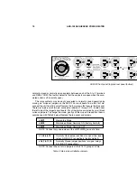
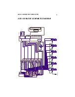
ASD-120 front panel (top) and rear panel (bottom)
120 VAC
60HZ
MAX LOAD
20A
INPUT 120 / 3 208 / 240 VAC
14400 WATTS
120 AMPS MAX
WARNING! ELECTRIC SHOCK HAZARD.
CONNECTION OF A POWER INPUT CABLE
TO THIS DEVICE AND TO A POWER SOURCE
MUST BE DONE BY QUALIFIED PERSONNEL
ONLY.
AVIS:
RISQUE DE CHOC
ELECTRIQUE -- NE PAS OUVRIR
RISK OF ELECTRIC SHOCK.
DO NOT OPEN. REFER
SERVICING TO QUALIFIED
SERVICE PERSONNEL. TO
REDUCE THE RISK OF FIRE
OR ELECTRIC SHOCK DO NOT
EXPOSE THIS EQUIPMENT TO
RAIN AND MOISTURE.
CAUTION!
MADE IN THE USA
A
B
C
F
E
D
B


