Fujitsu PRIMERGY RX300 S8 Скачать руководство пользователя страница 452

452

Upgrade and Maintenance Manual

 RX300 

S8

Conversion configurations

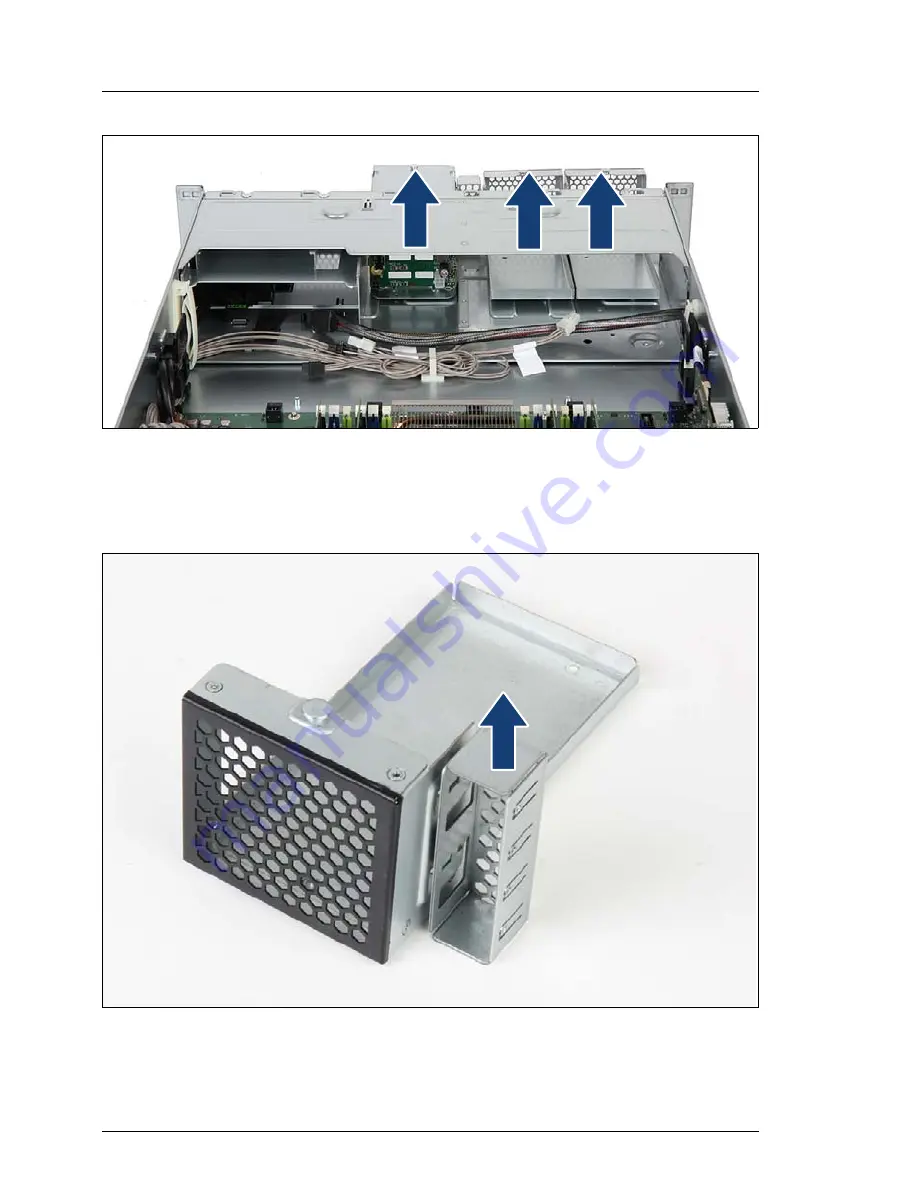
Figure 303: Removing the HDD cage and 2.5-inch dummy cages

Ê

Remove all cables from the HDD cage backplane.

Ê

Remove the HDD cage and the dummy cages from bay 1 and 2.

Figure 304: Removing the cover plate from the 2.5-inch dummy cage

Ê

Remove the cover plate from the dummy cage.

Содержание PRIMERGY RX300 S8

Страница 1: ...Upgrade and Maintenance Manual English PRIMERGY RX300 S8 Server Upgrade and Maintenance Manual Edition February 2014 ...

Страница 2: ...on mbH www cognitas de Copyright 2014 Fujitsu Technology Solutions GmbH All rights reserved Delivery subject to availability right of technical modifications reserved All hardware and software names used are trademarks of their respective manufacturers The contents of this manual may be revised without prior notice Fujitsu assumes no liability for damages to third party copyrights or other rights ...

Страница 3: ...of these components beyond their operating life may result in electrolyte leakage or depletion potentially causing emission of foul odor or smoke As a guideline in a normal office environment 25 C operating life is not expected to be reached within the maintenance support period 5 years However operating life may be reached more quickly if for example the product is used in a hot environment The c...

Страница 4: ...al Computer issued by JEITA the Japan Electronics and Information Technology Industries Association Technology controlled by the Foreign Exchange and Foreign Trade Control Law of Japan Documents produced by Fujitsu may contain technology controlled by the Foreign Exchange and Foreign Trade Control Law of Japan Documents which contain such technology should not be exported from Japan or transferred...

Страница 5: ...8 Upgrade and Maintenance Manual Only for the Japanese market I Although described in this manual some sections do not apply to the Japanese market These options and routines include CSS Customer Self Service ...

Страница 6: ...eason for update preview Initial release review corrections confirmation corrections tape RDX with USB 2 0 iRMC S4 September 2013 corrections February 2014 TFM screw removing TPM CE conformity RAID array rebuilt Cool safe Expansion card overview and installations sequence ...

Страница 7: ...ortant information 39 3 1 Safety instructions 39 3 2 ENERGY STAR 47 3 3 CE conformity 47 3 4 FCC Class A Compliance Statement 48 3 5 Environmental protection 49 4 Basic hardware procedures 51 4 1 Using diagnostics information 51 4 1 1 Locating the defective server 51 4 1 2 Determining the error class 52 4 1 2 1 Global Error indicator 52 4 1 2 2 Customer Self Service CSS indicator 52 4 1 3 Locating...

Страница 8: ...Disabling BitLocker functionality 73 5 1 2 Disabling SVOM boot watchdog functionality 74 5 1 2 1 Viewing boot watchdog settings 74 5 1 2 2 Configuring boot watchdog settings 75 5 1 3 Removing backup and optical disk media 76 5 1 4 Verifying and configuring the backup software solution 77 5 1 5 Note on server maintenance in a Multipath I O environment 77 5 1 6 Switching on the ID indicator 80 5 2 C...

Страница 9: ... 1 After replacing upgrading LAN controllers 99 5 2 17 2 After replacing the system board 99 5 2 18 Switching off the ID indicator 100 5 2 19 Performing a fan test after replacing a defective fan 100 6 Power supply units 103 6 1 Basic information 103 6 1 1 Power supply unit configurations 104 6 1 2 Assembly rules 104 6 2 Installing hot plug power supply units 105 6 2 1 Preliminary steps 105 6 2 2 ...

Страница 10: ... Mounting order 122 7 2 1 2 HDD naming scheme 123 7 2 2 4x3 5 inch HDD configuration with tape RDX drive 123 7 2 2 1 Mounting order with tape RDX drive 123 7 2 2 2 HDD naming scheme with tape drive 124 7 2 3 Installing 3 5 inch HDD modules 124 7 2 3 1 Preliminary steps 124 7 2 3 2 Removing a 3 5 inch dummy module 125 7 2 3 3 Installing a 3 5 inch HDD module 126 7 2 3 4 Concluding steps 127 7 2 4 R...

Страница 11: ...my module 136 7 3 2 3 Installing a 2 5 inch HDD SSD module 137 7 3 2 4 Concluding steps 138 7 3 3 Removing 2 5 inch HDD SSD modules 138 7 3 3 1 Preliminary steps 138 7 3 3 2 Removing a 2 5 inch HDD SSD module 139 7 3 3 3 Installing a 2 5 inch dummy module 140 7 3 3 4 Concluding steps 141 7 3 4 Replacing a 2 5 inch HDD SSD module 141 7 3 4 1 Preliminary steps 142 7 3 4 2 Removing a 2 5 inch HDD SSD...

Страница 12: ...uding steps 161 8 3 Removing the fan box 162 8 3 1 Preliminary steps 162 8 3 2 Removing the fan box 162 8 3 3 Installing the fan box 164 8 3 4 Concluding steps 165 9 Expansion cards and backup units 167 9 1 Basic information 167 9 2 Handling slot brackets 172 9 2 1 Installing a slot bracket 172 9 2 1 1 Installing a standard slot bracket 172 9 2 1 2 Installing a slot bracket to the Network adapter ...

Страница 13: ...SAS RAID controller 191 9 4 1 4 Connecting cables to the expansion card 192 9 4 1 5 Connecting a backup unit to the expansion card 192 9 4 1 6 Concluding steps 192 9 4 2 Removing the SAS RAID controller 193 9 4 2 1 Preliminary steps 193 9 4 2 2 Removing the SAS RAID controller 194 9 4 2 3 Concluding steps 194 9 4 3 Replacing the SAS RAID controller 195 9 4 3 1 Preliminary steps 195 9 4 3 2 Removin...

Страница 14: ...he BBU holder onto the air duct 211 9 6 2 5 Installing the air duct with a BBU 213 9 6 2 6 Concluding steps 214 9 6 3 Removing a BBU 215 9 6 3 1 Preliminary steps 215 9 6 3 2 Removing the air duct with a BBU 216 9 6 3 3 Removing the BBU holder from the air duct 217 9 6 3 4 Concluding steps 217 9 6 4 Replacing a BBU 218 9 6 4 1 Preliminary steps 218 9 6 4 2 Removing a BBU from the air duct 218 9 6 ...

Страница 15: ...P transceiver module 238 9 7 3 Replacing SFP transceiver modules 240 10 Main memory 243 10 1 Basic information 244 10 1 1 Memory sequence 245 10 1 1 1 Population rules 245 10 1 1 2 Independant Channel mode 247 10 1 1 3 Mirrored Channel and Performance modes 248 10 1 1 4 Rank Sparing mode 249 10 2 Installing memory modules 253 10 2 1 Preliminary steps 253 10 2 2 Installing a memory module 253 10 2 ...

Страница 16: ... 11 3 2 3 Closing the load plate 279 11 3 2 4 Installing the protective cover 280 11 3 2 5 Closing the load plate 282 11 3 3 Concluding steps 283 11 4 Upgrading or replacing processors 284 11 4 1 Preliminary steps 284 11 4 2 Upgrading or replacing a processor 284 11 4 3 Concluding steps 285 11 5 Handling processor heat sinks 286 11 5 1 Preliminary steps 286 11 5 2 Installing processor heat sinks 2...

Страница 17: ...5 1 Preliminary steps 307 12 5 2 Removing the ODD dummy module 307 12 5 3 Preparing an ODD 308 12 5 4 Installing an ODD 310 12 5 5 Concluding steps 310 12 6 Removing the optical disc drive ODD 311 12 6 1 Preliminary steps 311 12 6 2 Removing the ODD 312 12 6 3 Concluding steps 315 12 7 Replacing an ODD 315 12 7 1 Preliminary steps 316 12 7 2 Removing the defective ODD 316 12 7 3 Installing the new...

Страница 18: ... 2 Connecting the RDX drive to the USB 3 0 interface card 332 12 11 5 Concluding steps 335 12 12 Removing a tape RDX drive in 2 5 inch version 335 12 12 1 Preliminary steps 335 12 12 2 Removing the drive cage 336 12 12 3 Removing a tape RDX drive out of the cage 337 12 12 4 Concluding steps 339 12 13 Replacing the tape RDX drive in 2 5 inch version 339 12 13 1 Preliminary steps 339 12 13 2 Removin...

Страница 19: ...liminary steps 369 13 2 1 2 Removing the front panel module 369 13 2 1 3 Preparing the front panel module 370 13 2 1 4 Installing the front VGA connector 370 13 2 1 5 Re installing the front panel module 371 13 2 1 6 Concluding steps 372 13 2 2 Removing the front VGA connector 373 13 2 2 1 Preliminary steps 373 13 2 2 2 Removing the front VGA cable 373 13 2 2 3 Removing the front VGA connector 374...

Страница 20: ... 3 3 Removing the defective front LAN connector 392 13 3 3 4 Installing the new front LAN connector 392 13 3 3 5 Re installing the front panel module 392 13 3 3 6 Concluding steps 392 13 4 Front cage 393 13 4 1 Replacing the front panel cage 393 13 4 1 1 Preliminary steps 393 13 4 1 2 Removing the front panel cage 393 13 4 1 3 Re installing the front panel cage 395 13 4 1 4 Concluding steps 397 14...

Страница 21: ...423 14 4 3 1 Preliminary steps 423 14 4 3 2 Removing the TPM 424 14 4 3 3 Re installing the TPM 424 14 4 3 4 Concluding steps 425 14 5 Onboard SAS enabling key 425 14 5 1 Installing the onboard SAS enabling key 425 14 5 1 1 Preliminary steps 425 14 5 1 2 Installing the onboard SAS enabling key 426 14 5 1 3 Concluding steps 428 14 5 2 Removing the onboard SAS enabling key 428 14 5 2 1 Preliminary s...

Страница 22: ...ing in bay 5 447 15 3 Converting 448 15 3 1 Configuration 2 to configuration 4 448 15 3 2 Configuration 2 to configuration 7 451 15 3 3 Configuration 2 to configuration 3 455 15 3 4 Configuration 3 to configuration 6 458 15 3 5 Configuration 4 to configuration 7 461 15 3 6 Configuration 4 to configuration 8 463 15 3 7 Configuration 7 to configuration 8 464 15 4 Concluding steps 464 16 Cables 465 1...

Страница 23: ...ard configuration table 486 17 3 Connectors and indicators 487 17 3 1 Connectors and indicators on the system board 487 17 3 1 1 Onboard connectors 487 17 3 1 2 Onboard indicators and controls 489 17 3 2 Connectors and indicators on the I O panel 491 17 3 2 1 I O panel connectors 491 17 3 2 2 I O panel indicators 492 17 3 3 Connectors and indicators on the front panel 494 17 3 3 1 Front panel conn...

Страница 24: ...Upgrade and Maintenance Manual RX300 S8 Contents ...

Страница 25: ...ing defective hardware components This manual focuses on on site maintenance tasks It is recommended to prepare each service assignment following remote diagnostics procedures as described in the ServerView Suite Local Service Concept LSC manual see section Documents you need at hand on page 36 V CAUTION The document at hand comprises procedures of a wide range of complexity Check the profile of q...

Страница 26: ...at are being emphasized Ê describes activities that must be performed in the order shown Abc indicates keys on the keyboard V CAUTION Pay particular attention to texts marked with this symbol Failure to observe this warning may endanger your life destroy the system or lead to the loss of data I indicates additional information notes and tips indicates the procedure category in terms of complexity ...

Страница 27: ...dvanced Thermal Design option only components that support the higher operating range may be installed Further information on this is available in the configurator Installing optional components The operating manual of your server gives an introduction to server features and provides an overview of available hardware options Use the Fujitsu ServerView Suite management software and the iRMC web fro...

Страница 28: ... indicators of your server refer to the operating manual of your server and section Connectors and indicators on page 487 If the system has been powered off in order to replace a non hot plug unit a system of PRIMERGY diagnostic indicators guides you to the defective component The Indicate CSS button enables the indicator next to the defective component even if the server has been switched off and...

Страница 29: ...able Units CRU Customer Replaceable Units are intended for customer self service and may be installed or replaced as hot plug components during operation I Components that the customer is entitled to replace may differ according to the service form in his country Hot plug components increase system availability and guarantee a high degree of data integrity and fail safe performance Procedures can ...

Страница 30: ...fective Upgrade and Repair Units as customer replaceable CSS components Upgrade and repair procedures involve shutting down and opening the server V CAUTION The device may be seriously damaged or cause damage if it is opened without authorization or if repairs are attempted by unauthorized and untrained personnel Components that are handled as Upgrade Units Processors upgrade kits Optical disk dri...

Страница 31: ...ence with the system will void the warranty and exempt the manufacturer from all liability Components that are handled as Field Replaceable Units Processor replacement SAS SATA backplanes Power distribution board Front panel module Management and diagnostics modules System board Standard power supply unit Trusted Platform Module TPM USB Flash Module UFM 2 2 Average task duration The average task d...

Страница 32: ...ce task on page 73 Rack removal disassembly yes Making the server available removing the server from the rack if applicable Transport no Transporting the server to the service table where required depends on local customer conditions Maintenance procedures yes Maintenance procedures including preliminary and concluding software tasks Transport no Returning the server to its installation site where...

Страница 33: ...bracket to chassis Fan box M3 x 4 5 mm silver C26192 Y10 C67 Phillips PH2 No 2 hexagonal cross SW5 PZ2 0 6 Nm System board Front panel M3 x 6 mm silver C26192 Y10 C68 Torx TX10 0 6 Nm 3 5 inch HDD UNC 6 32 x 4 76 mm silver C26192 Y10 C27 Phillips PH0 No 0 0 4 Nm 2 5 inch HDD SSDs RDX DAT in 2 5 inch variant LTO drive M3 x 3 5 mm Wafer head screw silver C26192 Y10 C102 Table 2 List of required tool...

Страница 34: ...6 Nm UFM nylon screw M3 x 4 5 mm white A3C40109082 Phillips PH2 No 2 hexagonal cross SW5 PZ2 0 4 Nm Slot bracket to controller board M3 x 3 5 mm C26192 Y10 C151 Cross 0 2 Nm ODD latch delivered with the accessory pack M2 x 5 mm silver C26192 Y10 C63 Cylinder head Torx Plus 6 0 2 Nm ODD latch used by factory mounting M2 x 4 mm black C26192 Y10 C166 Screw driver Bit insert torque Screw Usage Type Ta...

Страница 35: ...start Phillips PH2 No 2 0 6 Nm USB 3 0 PCI card D3305 M3 x 5 mm silver contained in card kit S26361 D3305 A10 Phillips PH2 No 2 SW6 1 Nm heat sink captive screw Screw driver Bit insert torque Screw Usage Type Table 2 List of required tools and used screws ...

Страница 36: ...nstallation poster for initial operation available online ServerView Quick Start Guide ServerView クイックスタート ガイド for the Japanese market Information on initial server setup and software configuration available online Safety notes and regulations manual 安全上のご注意 for the Japanese market Important safety information available online or as a printed copy PRIMERGY RX300 S8 Server Operating Manual Availabl...

Страница 37: ...ble online or as a printed copy Returning used devices manual Recycling and contact information available online or as a printed copy Service Desk leaflet サポート サービス for the Japanese market Additional documentation iRMC S4 user guide available online RAID documentation available online at http manuals ts fujitsu com under Industry standard servers Expansion Cards Storage Adapters For the Japanese m...

Страница 38: ...38 Upgrade and Maintenance Manual RX300 S8 Before you start ...

Страница 39: ...tact your sales outlet or our customer service team The actions described in this manual shall be performed by technical specialists A technical specialist is a person who is trained to install the server including hardware and software Repairs to the device that do not relate to CSS failures shall be performed by service personnel Please note that unauthorized interference with the system will vo...

Страница 40: ...quirements for non industrial power supply networks for type A connectors The unit automatically adjusts itself to a mains voltage in a range of 100 VAC to 240 VAC Ensure that the local mains voltage lies within these limits This device must only be connected to properly grounded power outlets or connected to the grounded rack internal power distribution system with tested and approved power cords...

Страница 41: ...casing is completely assembled and the rear covers for the installation slots have been fitted electric shock cooling fire protection interference suppression Only install system expansions that satisfy the requirements and rules governing safety and electromagnetic compatibility and those relating to telecommunication terminals If you install other expansions they may damage the system or violate...

Страница 42: ...stallation detaching internal options in former device position To use a screw of the different kind can cause a breakdown of equipment The installation indicated on this document is sometimes changed to the kind of possible options without notice Batteries Incorrect replacement of batteries may lead to a risk of explosion The batteries may only be replaced with identical batteries or with a type ...

Страница 43: ...ve equipment damage and can fly out of the device danger of injury particularly to uncovered body parts such as the face or neck High humidity and airborne dust levels are to be avoided Electric shocks and or server failures may be caused by liquids such as water or metallic items such as paper clips entering a drive Shocks and vibrations are also to be avoided Do not insert any objects other than...

Страница 44: ...ot dry the CD DVD BD using devices such as a hair dryer To avoid dust damage and deformation keep the CD DVD BD in its case whenever it is not in use Do not store CDs DVDs BDs at high temperatures Areas exposed to prolonged direct sunlight or near heating appliances are to be avoided I You can prevent damage from the optical disk drive and the CDs DVDs BDs as well as premature wear of the disks by...

Страница 45: ...tic electricity To ensure reliable protection you must wear an earthing band on your wrist when working with this type of module and connect it to an unpainted conducting metal part of the system Any devices or tools that are used must be free of electrostatic charge Wear a suitable grounding cable that connects you to the external chassis of the system unit Always hold components with ESDs at the...

Страница 46: ...のご注意 Never lift the server into the rack using the handles on the front panel When connecting and disconnecting cables observe the relevant instructions in the Important Information chapter of the technical manual for the corresponding rack The technical manual is supplied with the corresponding rack When installing the rack make sure that the anti tilt protection is correctly fitted For safety re...

Страница 47: ...ses the properties guaranteed by ENERGY STAR can no longer be assured The ServerView Operations Manager user guide contains instructions for reading out measurement values including those relating to current energy consumption and air temperatures Either the Performance Monitor or the Task Manager can be used to read out CPU utilization levels The system complies with the requirements of the EC di...

Страница 48: ... harmful interference to radio or television reception which can be determined by turning the equipment off and on the user is encouraged to try to correct the interference by one or more of the following measures Reorient or relocate the receiving antenna Increase the separation between equipment and the receiver Connect the equipment into an outlet on a circuit different from that to which the r...

Страница 49: ...constantly switched on should be switched off until they are needed as well as during long breaks and after completion of work Packaging information This packaging information doesn t apply to the Japanese market Do not throw away the packaging You may need it later for transporting the system If possible the equipment should only be transported in its original packaging Information on handling co...

Страница 50: ...ing used devices manual via your local Fujitsu branch or from our recycling center in Paderborn Fujitsu Technology Solutions Recycling Center D 33106 Paderborn Tel 49 5251 525 1410 Fax 49 5251 525 32 1410 The device must not be disposed of with domestic waste This device is labeled in compliance with European directive 2002 96 EC on waste electrical and electronic equipment WEEE This directive set...

Страница 51: ...Illustrated Spares catalogs are available online at http manuals ts fujitsu com illustrated_spares EMEA market only Perform the following diagnostics procedures to identify defective servers and components 4 1 1 Locating the defective server When working in a datacenter environment switch on the ID indicator on the front and rear connector panels of the server for easy identification Ê Press the I...

Страница 52: ...ispatched to replace the part I The indicators also light up in standby mode and after a server restart due to a power failure 4 1 2 1 Global Error indicator Ê Check the Global Error indicator on the front or connector panel of the server Ê For further diagnostics proceed as follows Hardware errors Check the System Event Log SEL as described in section Viewing the SEL on page 92 Software agent rel...

Страница 53: ...tomer or field replaceable unit see section Determining the error class on page 52 4 1 3 2 Local diagnostic indicators on the system board Using the Indicate CSS button Ê Shut down and power off the server Ê Disconnect the AC power cord from the system I It is mandatory to disconnect power cords in order to use the Indicate CSS functionality Ê Press the Indicate CSS button to highlight defective c...

Страница 54: ...ance task Ê Verifying and configuring the backup software solution on page 77 Ê In case of Multipath I O environments please refer to section Note on server maintenance in a Multipath I O environment on page 77 Ê Removing backup and optical disk media on page 76 Ê Shut down the server I If the system is running an ACPI compliant operating system pressing the On Off button will perform a graceful s...

Страница 55: ...from the PSU cable clamp Ê Open on the locking lever on the PSU cable clamp 1 Ê Disconnect the power cord from the PSU and remove it from the cable tie 2 Removing the server from the direct current optional DC hot plug power supply unit I If there are installed two power supplies remove both power cords ...

Страница 56: ...g the server from the dc voltage Ê Remove the brown and the blue wire of the power cord from the current bar on the rack see Technical Manual of the rack system Ê Remove the wire labeled Ground from an appropriate earth ground Ê Open the 2 screws 1 Ê Disconnect the power cord from the PSU 2 ...

Страница 57: ...ments the server must not run while the top side cover is removed For further safety information please refer to chapter Important information on page 39 4 4 1 Extending the server out of the rack V CAUTION Use the anti tilt plate to prevent the rack from tipping when installing the rack Pulling the server out of the rack without having installed the anti tilt plate may cause the rack to tip over ...

Страница 58: ...ge 487 Ê If you are not using a cable mounting arm CMA kit ensure that the rear cables are long enough not to be strained or damaged when extending the server out of the rack Ê Fold down the two quick release levers on the rack mounting frame 1 and pull the server out of the rack until it locks in place 2 V CAUTION Do not use the extended server as a surface on which to put things or as a work sur...

Страница 59: ...e are needed to lift the server out of the rack cabinet For the Japanese market please refer to 安全上のご注意 Additionally a lifter is required in the following cases The server weighs more than 50 kg The server weighs more than 21 kg and is installed above the height of 25 U For configurations below 32 kg At least two people are needed to lift the server out of the rack cabinet For configurations below...

Страница 60: ...1 Ê Lift up the front of the server as shown so that the front and middle rack mounting bolts are disengaged from the mounting points on the telescopic rails Ê Lift the server out of the rear mounting points 3 and place it on an even surface 4 4 3 Opening the server V CAUTION Before removing or installing covers turn off the server and all peripheral devices Also unplug all power cables from the o...

Страница 61: ...cooling requirements the PRIMERGY RX300 S8 server must not run while the housing cover is removed For further safety information please refer to chapter Important information on page 39 4 4 3 1 Removing the housing cover Figure 6 Removing the housing cover Ê Open the locking lever 1 This will slide the top cover back disengaging the locking mechanism 2 Ê Remove the top cover 3 ...

Страница 62: ...t Figure 7 Removing the air duct V CAUTION Be carefull with the BBU or FBU cable If there is a BBU or FBU installed follow the procedure that is described in section Removing the air duct with a BBU on page 216 or in section Removing the air duct with an FBU on page 229 first Ê Remove the air duct ...

Страница 63: ...Upgrade and Maintenance Manual 63 Basic hardware procedures 4 5 Reassembling 4 5 1 Installing the air duct Figure 8 Installing the air duct guiding points I Regard that the air duct engages in the guiding points ...

Страница 64: ... or in section Installing the air duct with an FBU on page 226 4 5 2 Closing the server V CAUTION Before attaching the covers make sure no unnecessary parts or tools are left inside the server In order to comply with applicable EMC regulations regulations on electromagnetic compatibility and satisfy cooling requirements the PRIMERGY RX300 S8 server must not run while the housing cover is removed F...

Страница 65: ...ver surface Ê Lower the housing cover onto the chassis Ê Close the locking lever on the housing cover This will slide the housing cover shut engaging the locking mechanism 4 5 3 Mounting the server in the rack 4 5 3 1 Seating the server on the rack rails V CAUTION At least two people are needed to position the server on the rack rails For the Japanese market please refer to 安全上のご注意 For configurati...

Страница 66: ... I Refer to the rack cabinet manuals for more detailed information on other support systems Ê If required install the rack mounting bracket and rack system into the rack as described in the Rack Mounting Kit RMK F1 F2 DROP IN Quick Release Lever QRL Mounting Instructions I The printed poster is contained in the rack mounting kit For configurations below 55 kg At least three people are needed to li...

Страница 67: ...Ê Fully extend the telescopic rails until they lock in place 1 Ê At a slight angle lower the server onto the rear mounting point on the telescopic rails 2 Ê Fold down the server 3 Ensure that all six rack mounting bolts are properly seated in the mounting points on the telescopic rails and that the locking bars engage 4 ...

Страница 68: ...k release levers on the rack mounting frame lock into place Ê Reconnect all cables except the power cord to the server rear I If you are not using a cable mounting arm CMA kit ensure that the rear cables are long enough not to be strained or damaged when extending the server out of the rack Use cable ties to prevent loose cables from blocking the air flow For information on connecting and securing...

Страница 69: ...V Connecting power cords to the mains V CAUTION The power supply automatically adjusts to any mains voltage in the range of 100 VAC to 240 VAC You may only operate the server if its rated voltage range corresponds to the local mains voltage Figure 13 Securing power cord Ê Connect the power connector 1 to the power supply unit Ê Close the cable clamp around the power cord 2 and lock the cable clamp...

Страница 70: ...about 60 seconds until power on becomes possible Connecting the server to the direct current optional DC hot plug power supply unit Figure 14 Connecting the server to the dc voltage Ê Connect the power cord with the connector to the power supply unit of the server 1 Ê Attach the connector with the 2 screws 2 Ê Connect the wire labeled Ground to an appropriate earth ground Ê Connect the other two w...

Страница 71: ...agnetic compatibility and satisfy cooling requirements the PRIMERGY RX300 S8 server must not run while the housing cover is removed After connecting all power cords wait at least 60 seconds before pressing the On Off button Follow the safety instructions in chapter Important information on page 39 Ê Press the On Off button to start up the server Ê Perform the required procedures described in the c...

Страница 72: ...72 Upgrade and Maintenance Manual RX300 S8 Basic hardware procedures ...

Страница 73: ... files Enable BitLocker again after the maintenance procedure is complete V CAUTION With BitLocker features enabled modifying the system configuration hardware or firmware settings may render the system inaccessible The system may enter Recovery Mode and require a 48 digits recovery password to return to normal operation Ensure to disable BitLocker drive encryption before maintaining the server Wh...

Страница 74: ...so available in Japanese on the Fujitsu Extranet web pages 5 1 2 Disabling SVOM boot watchdog functionality The ServerView Operations Manager boot watchdog determines whether the server boots within a preset time frame If the watchdog timer expires the system will automatically reboot 5 1 2 1 Viewing boot watchdog settings Viewing boot watchdog settings in the BIOS Ê Enter the BIOS Ê Select the Se...

Страница 75: ...re detailed information refer to the ServerView Operations Manager Server Management user guide 5 1 2 2 Configuring boot watchdog settings If the system is to be started from removable boot media for firmware upgrade purposes the Boot watchdog needs to be disabled before starting maintenance task Otherwise the Boot watchdog might initiate a system reboot before the flash process is complete V CAUT...

Страница 76: ... or optical disk drive before removing it from the server Ê If the backup media cannot be ejected by conventional means and it is mandatory that the cartridge be removed prior to returning the drive for repair or disposing it a manual tape extraction needs to be performed For further information on forcible tape ejection please refer to the Tape Facts guide available to Fujitsu service partners fr...

Страница 77: ...ujitsu service partners from the Fujitsu Extranet pages 5 1 5 Note on server maintenance in a Multipath I O environment When booting your server offline from the ServerView Suite DVD to perform an offline BIOS firmware update using the ServerView Update DVD or collect diagnostic data using PrimeCollect in a Multipath I O environment there is a risk of damaging the system configuration which may le...

Страница 78: ... the Local System Update for PRIMERGY Servers user guide Ê Boot the server from the prepared Update DVD or USB stick DVD Ê Switch on the server Ê Right after switching on the server insert the Update DVD into the DVD drive and close the tray USB Ê Connect the USB stick to the server Ê Switch on the server If the server does not boot from DVD or USB stick proceed as follows Ê Reboot the server e g ...

Страница 79: ...e g by pressing the reset button on the front or switching the server off and then on again after a few seconds Ê Once the server has been started press F12 to enter the boot menu Ê Use the Ê and Ë cursor keys to select your DVD drive as boot device and press ENTER The server will now boot from the ServerView Suite DVD Ê After the boot process is complete select your preferred GUI language Ê In th...

Страница 80: ...495 Using the iRMC web frontend Ê Enter the ServerView iRMC web frontend Ê Under System Overview click Identify LED On to switch on the ID indicators Using ServerView Operations Manager Ê In ServerView Operations Manager Single System View press the Locate button in the title bar to switch on the ID indicators 5 2 Completing the maintenance task 5 2 1 Updating or recovering the system board BIOS a...

Страница 81: ...g or recovering the iRMC iRMC flash procedure I For the Japanese market follow the instructions provided separately Ê Prepare a USB stick including the bootable iRMC firmware update image Ê Connect the USB stick to the USB port I Ensure that only the USB device with the iRMC firmware is connected to the USB port Remove all other USB devices temporarily Ê Restart the server Ê The system will detect...

Страница 82: ...ding the bootable iRMC firmware update image Ê Ensure that the server has been shut down and disconnected from the mains as described in section Shutting down the server on page 54 Ê Connect the USB stick to the USB port I Ensure that only the USB device with the iRMC firmware is connected to the USB port Remove all other USB devices temporarily Ê Connect the server to the mains while pushing the ...

Страница 83: ...e Chassis ID EPROM After replacing the system board the backup data is restored from the Chassis ID board to the new system board In order to verify whether the backup or restore process has been successful check the System Event Log SEL using the ServerView Operations Manager see also section Viewing and clearing the System Event Log SEL on page 92 After replacing the system board Ê Check the SEL...

Страница 84: ... to update the RAID controller firmware using the ServerView Update Manager or Update Manager Express UME please refer to the following manuals ServerView Update Manager ServerView Update Management user guide ServerView Update Manager Express Local System Update for PRIMERGY Servers user guide Using the flash tool The latest firmware files are available as ASPs Autonomous Support Packages for Win...

Страница 85: ... Ê Enter the BIOS Ê From the Advanced menu select Option ROM Configuration Ê Identify the desired PCI slot and set its Launch Slot OpROM setting to Enabled Ê Save your changes and exit the BIOS I Up to two Option ROMs can be activated in the system board BIOS at a time For detailed information on how to access the BIOS and modify settings refer to corresponding BIOS Setup Utility reference manual ...

Страница 86: ...ures may differ depending on the backup software For details refer to the dedicated documentation provided separately Further information on suitable backup software solutions and related documentation is available to Fujitsu service partners from the Fujitsu Extranet pages Re enabling backup drives If a backup drive has been disabled or deleted from the backup software drive list as described in ...

Страница 87: ...Ê Exit the BIOS 5 2 6 2 Resetting the boot retry counter The boot retry counter should be reset to its original value concluding every service task I Please note if the customer does not know about the original boot retry values If the system boots up and no further errors occur within 6 hours after that successful boot attempt the boot retry counter will automatically be reset to its default valu...

Страница 88: ...t tries field Resetting the boot retry counter using iRMC web frontend Ê Enter the ServerView iRMC web frontend Ê Select the Server Management menu Ê The following boot retry counter settings are available under ASR R Options Ê Under Retry counter max specify the maximum number of attempts to boot the operating system 0 to 7 Ê Under Retry counter the current number of remaining boot attempts is di...

Страница 89: ... Setup Utility reference manual Configuring boot watchdog settings using the iRMC web frontend Ê Enter the ServerView iRMC web frontend Ê Select the Server Management menu Ê Under Watchdog Settings ensure that the check box next to Boot Watchdog is selected From the drop down list choose Reset and specify the desired timeout delay Ê Click Apply for the changes to take effect I For detailed informa...

Страница 90: ...current operation mode e g Mirrored Channel mode may no longer be available due to a lack of identical memory module pairs In this case the operation mode will automatically revert to Independent Channel Mode I For detailed information on memory operation modes available for your server refer to section Memory sequence on page 245 After replacing the defective module s the memory operation mode is...

Страница 91: ...strator whether the RTC or UTC time standard is to be used as system time I If the system time RTC is set to UTC the SEL System Event Log time stamps may differ from the local time Ê Enter the BIOS Ê Select the Main menu Ê Under System Time and System Date specify the correct time and date I By default the system time set in the BIOS is RTC Real Time Clock local time If your IT infrastructure reli...

Страница 92: ...ational events I Note on the SVOM Driver Monitor The Driver Monitor view gives you an overview of the monitored components as well as the associated events contained in the system event log on the managed server Under Monitored Components the monitored components are listed If a component has the status Warning or Error you can select it in the list and click Acknowledge This confirms the event on...

Страница 93: ...ose the Internal Event Log submenu Ê Under Internal Event Log Information click Clear Internal Event Log to clear the SEL I For detailed information on iRMC settings refer to the Integrated Remote Management Controller user guide 5 2 12 Updating the NIC configuration file in a Linux environment In order to prevent errors caused by changing network device names eth x it is recommended to store the ...

Страница 94: ...and Ignore to complete the boot process Ê Use the vi text editor to specify the MAC address in the HWADDR section of the ifcfg eth x file I The MAC address can be found on the type label attached to the system board or network controller Example In order to modify the definition file for network controller 1 enter the following command vi etc sysconfig network scripts ifcfg eth1 In vi specify the ...

Страница 95: ...y in order to boot the operating system Ê Ask the system administrator to enable BitLocker protection on the operating system drive using the BitLocker setup wizard available either from the Control Panel or Windows Explorer Ê Open Bitlocker Drive Encryption by clicking the Start button clicking Control Panel clicking Security and then clicking Bitlocker Drive Encryption I Administrator permission...

Страница 96: ...V CAUTION The system is now operational however data redundancy will not be available until the RAID array rebuild is complete Depending on the hard disk drive capacity the overall process can take up to several hours in some cases even days I You may notice a slight performance impact during rebuild 5 2 15 Looking up changed MAC WWN addresses When replacing a network controller the MAC Media Acce...

Страница 97: ...t as soon as the Emulex BIOS utility option appears press ALT E or CTRL E Ê Under Emulex Adapters in the System you will find all available Emulex adapters and their WWN addresses Ê Note down the new 16 digit WWN address Ê Press Esc to exit the Emulex BIOS utility Ê Inform the customer about the changed WWN address QLogic FC adapters Ê Enable the network controller s Option ROM in the system board...

Страница 98: ... Prom tool The tool and further instructions are available to maintenance personnel from the Fujitsu Technology Solutions Extranet https partners ts fujitsu com com service ps Servers PRIMERGY Ê Select your PRIMERGY system from the main area of the page Ê From the categories selection choose Software Tools Documentation Ê In the Tools area click Tools Chassis IDProm Tool to download the file tool ...

Страница 99: ... Team Statistics Available statistics about the selected LAN team I For more detailed information refer to the ServerView Operations Manager Server Management user guide 5 2 17 1 After replacing upgrading LAN controllers Please note when re using a replaced LAN controller Ê Confirm with the customer whether the LAN controller you have replaced has been used as part of a LAN teaming configuration Ê...

Страница 100: ... the ID button on the front panel Ê Press the ID button on the front panel to switch off the ID indicators Using the iRMC web frontend Ê Enter the ServerView iRMC web frontend Ê Under System Overview click Identify LED Off to switch off the ID indicators Using ServerView Operations Manager Ê In ServerView Operations Manager Single System View and press the Locate button in the title bar to switch ...

Страница 101: ...clicking GO In the left hand section of the window the Configuration tab is being activated Ê In the navigation area of the Configuration tab select Other Settings Ê Under Daily Fan Test set the daily fan test time to a few minutes from the current time Ensure to note down your previous setting Ê Click Save Page The fan test will be started at the specified time Ê After the fan test is complete re...

Страница 102: ... Maintenance Manual RX300 S8 Basic software procedures Ê Enter IPMIVIEW EXE and press Enter to start the IPMI Tool Ê Under System Specific Functions select Fan Test and press the F9 function key to start the fan test ...

Страница 103: ...rop it by mistake injuries may result For further safety information please refer to chapter Important information on page 39 6 1 Basic information The PRIMERGY RX300 S8 server can be equipped with up to two power supply units that automatically adjust to any mains voltage in the range of 100 VAC to 240 VAC or with up to two DC power supply units that adjusts automatically to any power voltage in ...

Страница 104: ... comply with applicable EMC regulations and satisfy cooling requirements For an redundent power suppy you need two hot plug power supply units I Note for servers using CMA Cable Management Arm Regarding of removing power supply units additional tasks are needed due to an interference between CMA stopper and the power supply units Ê Unlock the CMA stopper Ê Remove the CMA stopper with the mounted c...

Страница 105: ...talling hot plug power supply units 6 2 1 Preliminary steps No steps needed 6 2 2 Removing the dummy cover Figure 17 Removing the dummy cover Ê Press in on both release latches 1 and remove the dummy cover 2 Customer Replaceable Unit CRU Hardware 5 minutes Tools tool less ...

Страница 106: ...ions and satisfy cooling requirements 6 2 3 Installing a hot plug power supply unit Figure 18 Installing the hot plug power supply unit Ê Push the power supply unit into its bay 1 as far as it will go until the release latch snaps in place 2 Ê Fold down the handle on the power supply unit 3 V CAUTION Ensure that the power supply unit properly engages in its bay and is locked in position in order t...

Страница 107: ...s Ê Unlock the CMA stopper Ê Remove the CMA stopper with the mounted crossbar Ê Support the CMA stopper the crossbar and the CMA including cables with your right hand Ê Remove the power supply unit and install a dummy cover into the empty bay Ê Remount the complete assembly CMA stopper crossbar and CMA into the rail 6 3 1 Preliminary steps Ê Locating the defective server on page 51 Ê Remove the po...

Страница 108: ...ower supply unit halfway upward in the direction of the arrow 2 Ê Push the green release latch in direction of the arrow 1 Ê While keeping the green release latch pressed pull the power supply unit out of its slot 3 V CAUTION Never leave the bay for the power supply unit empty for more than two minutes during operation Otherwise excessive temperatures could damage system components ...

Страница 109: ... the impressed arrow symbol facing up Ê Press in on both release latches on the dummy cover 1 and carefully insert the dummy cover into its bay 2 until it locks in place V CAUTION Always install dummy covers into unused bay ts to comply with applicable EMC regulations and satisfy cooling requirements 6 3 4 Concluding steps Ê Connecting the server to the power source on page 69 ...

Страница 110: ...new unit of the same type 6 4 1 Preliminary steps Ê Locating the defective server on page 51 Ê Disabling BitLocker functionality on page 73 Ê Locating the defective component on page 53 Ê In non redundant power supply configurations shut down the server as described in section Shutting down the server on page 54 Ê Disconnecting power cords on page 54 6 4 2 Removing the defective hot plug power sup...

Страница 111: ...re that the power supply unit properly engages in its slot and is locked in position in order to prevent it from sliding out of the chassis during transportation Ê If applicable fold down the handle on the power supply unit 3 6 4 4 Concluding steps Ê Connecting the server to the power source on page 69 Ê In non redundant PSU configurations swich on the server as described in section Switching on t...

Страница 112: ... redundant power supplyconfigurations shut down the server as described in section Shutting down the server on page 54 Ê Disconnecting power cords on page 54 6 5 2 Removing the hot plug power supply unit V CAUTION If you want to upgrade the power supply unit from 450W to 800 W hot plug the running of the mixed configuration must not exceed 5 minutes Ê Removing a hot plug power supply unit on page ...

Страница 113: ...W to 800 W power supply unit please note the following After replacing the first power supply unit the CSS indicator will start flashing entry into SEL indicating an unsupported mixture of power supply units with different power output The CSS indicator LED will stop flashing as soon as the second power supply unit has been replaced as well V CAUTION Ensure that the power supply unit properly enga...

Страница 114: ...cing the power backplane 6 6 1 Preliminary steps Ê Locating the defective server on page 51 Ê Disabling BitLocker functionality on page 73 Ê Shutting down the server on page 54 Ê Disconnecting power cords on page 54 Ê Getting access to the component on page 57 Ê Removing the housing cover on page 61 Ê Removing the air duct on page 62 Field Replaceable Unit FRU Hardware 10 minutes Tools tool less ...

Страница 115: ...RX300 S8 Upgrade and Maintenance Manual 115 Power supply units 6 6 2 Disconnecting power cables Figure 23 Disconnecting cables from the power backplane Ê Remove the cables from the power backplane ...

Страница 116: ...Maintenance Manual RX300 S8 Power supply units 6 6 3 Removing the power backplane Figure 24 Removing the power backplane A Ê Unlock the locking mechanism of the power backplane Figure 25 Removing the power backplane B ...

Страница 117: ...grade and Maintenance Manual 117 Power supply units Ê Fold the power backplane in the direction of the arrow Figure 26 Removing the power backplane C Ê Push the power backplane upward Ê Remove the power backplane ...

Страница 118: ...units 6 6 4 Installing the power backplane Figure 27 Installing the power backplane A Ê Insert the new power backplane into the guiding hooks of the chassis 1 Figure 28 Installing the power backplane B Ê Slide the power backplane downward in the guiding hooks ...

Страница 119: ...RX300 S8 Upgrade and Maintenance Manual 119 Power supply units Figure 29 Locking the power backplane Ê Press the power backplane in the direction of the arrow to lock it ...

Страница 120: ...e air duct on page 63 Ê Mounting the housing cover on page 65 Ê Sliding the server into the rack on page 68 If the server has been completely removed from the rack for maintenance purposes reinstall and secure it in the rack as described in section Mounting the server in the rack on page 65 Ê Connecting the server to the power source on page 69 Ê Enabling BitLocker functionality on page 95 ...

Страница 121: ... This does not indicate a failure Depending on the OS you can configure the write cache settings for the hard disk drives If a power failure should occur while the write cache is enabled cached data may be lost When disposing of transferring or returning a hard disk or solid state drive wipe out the data on the drive for your own security Rough handling of hard disk drives may damage the stored da...

Страница 122: ...t bus technologies SAS or SATA first install SAS drives and then SATA drives Please refer to sections Mounting order for 2 5 inch HDDs SSDs on page 131 and 6x3 5 inch HDD configuration on page 122 for a complete overview of the mounting sequence Install dummy modules into unused HDD SSD bays I The mounting order described above is only relevant for the factory manufacturing process In case of upgr...

Страница 123: ...Manager differs from the HDD mounting order 7 2 2 4x3 5 inch HDD configuration with tape RDX drive 7 2 2 1 Mounting order with tape RDX drive I Maximum configuration 4x 3 5 inch HDDs Figure 32 3 5 inch HDD mounting order with tape 3 5 inch HDDs HDD RAID Manager Channel HDD RAID Manager Channel 1 0 1 2 4 2 3 1 1 4 5 2 5 2 1 6 6 2 Table 4 HDD naming scheme tape ...

Страница 124: ...ager differs from the HDD mounting order 7 2 3 Installing 3 5 inch HDD modules 7 2 3 1 Preliminary steps Ê Locate the correct drive bay as described in section 6x3 5 inch HDD configuration on page 122 3 5 inch HDDs HDD RAID Manager Channel HDD RAID Manager Channel 1 0 1 2 4 2 3 1 1 4 2 1 Table 5 HDD naming scheme Customer Replaceable Unit CRU Hardware 5 minutes Tools tool less ...

Страница 125: ...ng an additional HDD the dummy module needs to be removed from the desired drive bay Ê Press in on the locking tabs on both sides of the dummy module to disengage the locking mechanism 1 Ê While keeping the locking tabs pressed pull the dummy module out of its bay 2 V CAUTION Save the dummy module for future use Always replace dummy modules into unused HDD bays to comply with applicable EMC regula...

Страница 126: ...module Figure 34 Opening the 3 5 inch HDD module locking lever Ê While pressing down on the locking button 1 fold up the lever 2 Figure 35 Inserting the 3 5 inch HDD module Ê Insert the HDD module into a drive bay and carefully push back as far as it will go 1 Ê Fold down the lever to lock the HDD module in place 2 ...

Страница 127: ...e the array using ServerView RAID Manager Customer Replaceable Unit CRU Hardware 5 minutes Tools tool less RAID level Procedure RAID 0 Only remove an HDD module combined in a RAID 0 array if defective V CAUTION Removing an operational HDD module will result in data loss RAID 1 RAID 5 Removing an HDD module from a RAID 1 or RAID 5 array will not result in data loss However the removed drive needs t...

Страница 128: ...efer to the ServerView Suite RAID Management user guide 7 2 4 2 Removing a 3 5 inch HDD module Figure 36 Removing a 3 5 inch HDD module Ê While pressing down on the locking button 1 fold up the lever 2 I Thereby the HDD module is pushed out of its drive bay by about 1 cm and disconnected from the SAS SATA backplane Ê Wait about 30 seconds to allow the hard disk drive to spin down Ê Pull the HDD mo...

Страница 129: ...odule is not replaced immediately always replace a dummy module into the unused HDD bay to comply with applicable EMC regulations and satisfy cooling requirements Figure 37 Installing a 3 5 inch dummy module Ê Slide the 3 5 inch dummy module into the drive bay until it locks in place 7 2 4 4 Concluding steps Ê Performing a RAID array rebuild on page 96 ...

Страница 130: ... in conjunction with a corresponding RAID configuration All HDD SSD modules drives must be uniquely identified so that they can be reinstalled in their original mounting locations later If this is not done existing data can be lost 7 2 5 1 Preliminary steps Ê Locating the defective server on page 51 Ê Locate the defective HDD module as described in section Local diagnostic indicators on the front ...

Страница 131: ...ch HDDs SSDs Basic information Solid state drives SSDs are always equipped before installing hard disk drives If only one HDD SSD module is installed the HDD SSD module will be installed in position 1 Empty bays must be equipped with a dummy module 7 3 1 1 HDD SSD mounting order for 4x 2 5 inch HDD SSD configuration Figure 38 2 5 inch HDD SSD mounting order configuration 2 and 3 7 3 1 2 HDD SSD na...

Страница 132: ... 7 3 1 3 HDD SSD mounting order for 8x 2 5 inch HDD SSD configurations Figure 39 2 5 inch HDD SSD mounting order configuration 4 Figure 40 2 5 inch HDD SSD mounting order configuration 6 2 5 inch HDDs SSDs HDD RAID Manager Channel 1 0 1 2 1 1 3 2 1 4 3 1 Table 6 HDD naming scheme ...

Страница 133: ...SSD configurations I The HDD SSD numbering as listed in the ServerView RAID Manager differs from the HDD mounting order 7 3 1 5 HDD SSD mounting order for 12x 2 5 inch HDD SSD configuration Figure 42 2 5 inch HDD SSD mounting order configuration 7 2 5 inch HDDs SSDs HDD RAID Manager Channel HDD RAID Manager Channel 1 0 1 2 4 2 3 1 1 4 5 2 5 2 1 6 6 2 7 3 1 8 7 2 Table 7 HDD naming scheme ...

Страница 134: ...ion I The HDD SSD numbering as listed in the ServerView RAID Manager differs from the HDD mounting order 7 3 1 7 HDD SSD mounting order for 12x 2 5 inch HDD SSD configuration Figure 43 2 5 inch HDD SSD mounting order configuration 8 2 5 inch HDDs SSDs HDD RAID Manager 1 0 2 1 3 2 4 3 5 4 6 5 7 6 8 7 9 8 10 9 11 10 12 11 Table 8 HDD naming scheme ...

Страница 135: ...I The HDD SSD numbering as listed in the ServerView RAID Manager differs from the HDD mounting order 7 3 2 Installing 2 5 inch HDD SSD modules 2 5 inch HDDs SSDs HDD RAID Manager 1 0 2 12 3 1 4 13 5 2 6 14 7 3 8 15 9 4 10 5 11 6 12 7 13 8 14 9 15 10 16 11 Table 9 HDD naming scheme Customer Replaceable Unit CRU Hardware 5 minutes Tools tool less ...

Страница 136: ...order for 2 5 inch HDDs SSDs on page 131 7 3 2 2 Removing a 2 5 inch dummy module Figure 44 Removing a 2 5 inch dummy module Ê Press both tabs together 1 and pull the dummy module out of its bay 2 V CAUTION Save the dummy module for future use Always replace dummy modules into unused HDD SSD bays to comply with applicable EMC regulations and satisfy cooling requirements ...

Страница 137: ...d disk drives solid state drives 7 3 2 3 Installing a 2 5 inch HDD SSD module Figure 45 Opening the 2 5 inch HDD SSD module locking lever Ê Pinch the green locking clips 1 and open the locking lever 2 Figure 46 Inserting the 2 5 inch HDD SSD module ...

Страница 138: ...a RAID array please proceed as follows Customer Replaceable Unit CRU Hardware 5 minutes Tools tool less RAID level Procedure RAID 0 Only remove an HDD module combined in a RAID 0 array if defective V CAUTION Removing an operational HDD module will result in data loss RAID 1 RAID 5 Removing an HDD module from a RAID 1 or RAID 5 array will not result in data loss However the removed drive needs to b...

Страница 139: ...urther information please refer to the ServerView Suite RAID Management user guide V CAUTION All data on all HDDs SSDs in the array will be lost Be sure to back up your data before deleting a RAID array I For further information please refer to the ServerView Suite RAID Management user guide 7 3 3 2 Removing a 2 5 inch HDD SSD module Figure 47 Disconnecting a 2 5 inch HDD SSD module Ê Pinch the gr...

Страница 140: ...hen removing a solid state drive Figure 48 Removing a 2 5 inch HDD SSD module Ê Pull the HDD SSD module completely out of its bay 7 3 3 3 Installing a 2 5 inch dummy module V CAUTION If the removed HDD SSD module is not replaced immediately always replace a dummy module into the unused HDD SSD bay to comply with applicable EMC regulations and satisfy cooling requirements ...

Страница 141: ... in place 7 3 3 4 Concluding steps Ê Performing a RAID array rebuild on page 96 7 3 4 Replacing a 2 5 inch HDD SSD module V CAUTION Only remove an HDD SSD module during operation if the drive is not currently being accessed Observe the indicators for the corresponding HDD SSD modules see operating manual of your server Customer Replaceable Unit CRU Hardware 5 minutes Tools tool less ...

Страница 142: ...ng data can be lost 7 3 4 1 Preliminary steps Ê Locating the defective server on page 51 Ê Locate the defective HDD SSD module as described in section Local diagnostic indicators on the front on page 53 Only applicable for removing intact HDD SSD modules Ê Before removing a non defective HDD SSD module put the drive into Offline mode using your RAID configuration software 7 3 4 2 Removing a 2 5 in...

Страница 143: ...ng down the server on page 54 Ê Disconnecting power cords on page 54 Ê Remove all HDD SSD modules from the server as described in section Removing 3 5 inch HDD modules on page 127 V CAUTION Ensure that all hard disk drives are uniquely identified so that you can reinsert them into their original bays after replacing the HDD backplane Ê Getting access to the component on page 57 Ê Removing the fan ...

Страница 144: ...rd disk drives solid state drives 7 4 1 2 Removing the 3 5 inch HDD SAS SATA backplane Figure 50 Disconnecting cables from the 3 5 inch HDD SAS SATA backplane Ê Disconnect all cables from the 3 5 inch HDD SAS SATA backplane SAS cables Power cables ...

Страница 145: ...oving the 3 5 inch HDD SAS SATA backplane A Ê Unlock the 3 5 inch HDD SAS SATA backplane 1 and push the SAS SATA backplane in the direction of the arrow 2 until it unlocks out of the locking noses and the locking mechanism on the bottom of the server Ê Remove the 3 5 inch HDD SAS SATA backplane ...

Страница 146: ...nstalling the 3 5 inch HDD SAS SATA backplane A Ê At a slight angle insert the 3 5 inch HDD SAS SATA backplane into the guide 1 Ê Fit the 3 5 inch HDD SAS SATA backplane on the eight hooks circles 2 Ê Push the3 5 inch HDD SAS SATA backplane in the direction of the arrow 3 I Ensure that the eight hooks project through the recesses in the backplane ...

Страница 147: ...3 5 inch HDD SAS SATA backplane B Ê Reconnect all cables to the 3 5 inch HDD SAS SATA backplane Power cable C5 to connector X10 Power cable C3 to connector X9 SAS cable C8 to connector X1 SAS cable C9 to connector X2 I For a complete cabling overview please refer to section List of used cables on page 465 ...

Страница 148: ...backplane 7 4 2 1 Preliminary steps Ê Locating the defective server on page 51 Ê Disabling BitLocker functionality on page 73 Ê Shutting down the server on page 54 Ê Disconnecting power cords on page 54 Ê Remove all HDD SSD modules from the server as described in section Removing 2 5 inch HDD SSD modules on page 138 V CAUTION Ensure that all hard disk drives are uniquely identified so that you can...

Страница 149: ... 2 Removing the HDD cage Figure 54 Disconnecting cables from the 4x 2 5 inch HDD SAS backplane Ê Disconnect all cables from the 4x 2 5 inch HDD SAS backplane SAS SATA cable Power cable Figure 55 Removing the HDD cage Ê Remove the screws of the HDD cage Ê Slide the HDD cage frontward out ...

Страница 150: ...nce Manual RX300 S8 Hard disk drives solid state drives 7 4 2 3 Removing the 4x 2 5 inch SAS HDD backplane Figure 56 Removing the 4x 2 5 inch HDD SAS backplane Ê Remove the screw 1 Ê Remove the 4x 2 5 inch HDD SAS backplane 2 ...

Страница 151: ...ves 7 4 2 4 Installing the 4x 2 5 inch HDD SAS backplane Figure 57 Installing the 2 5 inch HDD SAS backplane Ê Insert the 4x 2 5 inch HDD SAS backplane in that way that it is in the guiding recesses see circles Ê Fasten the 4x2 5 inch HDD SAS backplane with the screw see arrow ...

Страница 152: ...ch HDD cage Ê Secure the 2 5 inch HDD SAS backplane on the drive cage with the screws Figure 59 Reconnecting cables to the 4x 2 5 inch HDD SAS backplane Ê Reconnect all cables to the 2 5 inch HDD SAS backplane Power cable to SAS backplane connector X6 If applicable power cable to SAS backplane connector X9 SAS cable to backplane connectors X1 ...

Страница 153: ...71 Ê Enabling BitLocker functionality on page 95 7 4 3 Replacing the 12x 2 5 inch HDD SAS backplane 7 4 3 1 Preliminary steps I The 2 5 inch HDD SAS backplane is mounted on the drive cages It is not necessary to remove the drive cage before replacing the SAS SATA backplane Ê Locating the defective server on page 51 Ê Disabling BitLocker functionality on page 73 Ê Shutting down the server on page 5...

Страница 154: ... reinsert them into their original bays after replacing the HDD backplane Ê Getting access to the component on page 57 Ê Removing the fan box on page 162 7 4 3 2 Removing the 12x2 5 inch HDD SAS backplane Figure 60 Disconnecting cables from the 12x 2 5 inch HDD SAS backplane Ê Disconnect all cables from the 12x 2 5 inch HDD SAS backplane SAS cables Power cables ...

Страница 155: ...he three screws of the 12x 2 5 inch HDD SAS backplane see circles Ê Tilt out the 12x 2 5 inch HDD SAS backplane as shown Ê At a slight angle unhinge the 12x 2 5 inch HDD SAS backplane from the guides on the drive cage and remove it 7 4 3 3 Installing the 12x 2 5 inch HDD SAS backplane Figure 62 Installing the 12x 2 5 inch HDD SAS backplane A ...

Страница 156: ...63 connecting cables tothe 12x 2 5 inch HDD SAS backplane Ê Reconnect all cables to the 12x 2 5 inch HDD SAS backplane Power cable C4 connected to SAS backplane connector X15 Power cable C5 connected to SAS backplane connector X17 SAS cable C9 connected to SAS controller connector MLC1 to primary backplane connectors X1 SAS cable C9 connected to SAS controller connector MLC2 to secondary backplane...

Страница 157: ...es 7 4 3 4 Concluding steps Ê Installing the fan box on page 164 Ê Reassembling on page 63 Ê Installing 2 5 inch HDD SSD modules on page 135 Ê Connecting the server to the power source on page 69 Ê Switching on the server on page 71 Ê Enabling BitLocker functionality on page 95 ...

Страница 158: ...158 Upgrade and Maintenance Manual RX300 S8 Hard disk drives solid state drives ...

Страница 159: ...ded object before handling electrostatic sensitive devices ESDs Do not touch the circuitry on boards or soldered parts Hold circuit boards by their metallic areas or edges If devices are installed or disassembled using methods other than those outlined in this chapter the warranty will be invalidated For further information please refer to chapter Important information on page 39 8 1 Basic informa...

Страница 160: ... 51 Ê Getting access to the component on page 57 Ê Locating the defective component on page 53 8 2 2 Removing a system fan I Please notice the advices for redundancy Figure 64 Removing a system fan Ê Take the system fan by the green touch points Ê Lift the system fan out of the fan box Upgrade and Repair Unit URU Hardware 5 minutes Tools tool less ...

Страница 161: ...teps Ê Reassembling on page 63 I When a system fan module fails the remaining fans will start operating at full speed After the defective fan module has been replaced all fans will continue to run at full speed for a couple of minutes before resetting to a lower speed Ensure that all system fans reset to a normal operating speed Ê Performing a fan test after replacing a defective fan on page 100 r...

Страница 162: ...hutting down the server on page 54 Ê Disconnecting power cords on page 54 Ê Getting access to the component on page 57 8 3 2 Removing the fan box Figure 66 Removing a fan module Ê Take the two system fans by the green touch points and lift the system fans out of the fan box Upgrade and Repair Unit URU Hardware 5 minutes Tools screw driver FAN 2 FAN 4 ...

Страница 163: ...rade and Maintenance Manual 163 System fan Figure 67 Removing the fan box Ê Remove the two screws Figure 68 Removing the fan box Ê Take the fan box by the green touch points and lift the fan box out of the chassis ...

Страница 164: ... Manual RX300 S8 System fan 8 3 3 Installing the fan box Figure 69 Installing the fan box Ê Take the fan box by the green touch points and insert the fan box Figure 70 Installing the fan box Ê Fasten the fan box with the 2 screws ...

Страница 165: ...ual 165 System fan Ê Install the two fan modules see section Installing a system fan on page 161 8 3 4 Concluding steps Ê Reassembling on page 63 Ê Connecting the server to the power source on page 69 Ê Switching on the server on page 71 ...

Страница 166: ...166 Upgrade and Maintenance Manual RX300 S8 System fan ...

Страница 167: ... and soldered parts of internal options are exposed and can be damaged by static electricity Always discharge static build up e g by touching a grounded object before handling electrostatic sensitive devices ESDs Do not touch the circuitry on boards or soldered parts Hold circuit boards by their metallic areas or edges If devices are installed or disassembled using methods other than those outline...

Страница 168: ...ce Function 1 PCIe Gen 3 x8 x8 preferred slot for Modular LAN controller with NCSI connector CPU1 2 PCIe Gen 3 x8 x8 CPU1 3 PCIe Gen 3 x8 x8 CPU1 4 PCIe Gen 3 x16 x8 CPU1 5 PCIe Gen 3 x16 x16 only available with CPU2 6 PCIe Gen 3 x16 x16 only available with CPU2 7 PCIe Gen 3 x8 x8 slot for SAS RAID controller Slot 7 Slot 6 Slot 5 Slot 4 Slot 3 Slot 2 Slot 1 ...

Страница 169: ...SAS RAID D2616 RAID Ctrl SAS 6G 5 6 512 MB x8 PCI2 0 1 1 D3116C RAID Ctrl SAS 6G1GB x8 PCI3 0 1 1 D2607 RAID Ctrl SAS 6G 0 1 x8 PCI2 0 1 1 9286CV RAID Ctrl SAS 6G 8 ex 1GB LSI V3 x8 PCI3 0 4 4 1 5 3 2 Modular LAN D2755 Dual Port SFP x8 PCI2 0 1 1 D3045 Quad Port x4 PCI2 0 1 1 D2745 x4 PCI2 0 1 1 D3035 Dual Port x4 PCI2 0 1 1 D2735 x4 PCI2 0 1 1 PCIe SSD FusionIO 365 GB MLC x8 PCI2 0 2 4 1 3 2 785 ...

Страница 170: ...IB EP QLE7342e x8 PCI2 0 2 6 5 2 4 3 1 SAS Backup LSI SAS 9200 8e x8 PCI2 0 3 4 2 3 1 6 5 FC LPe 16000 16Gbit x8 PCI3 0 4 6 5 1 4 3 2 LPe 16002 16Gbit x8 PCI3 0 4 6 5 1 4 3 2 LPe 1250 8Gbit x4 PCI2 0 4 6 5 1 4 3 2 LPe 12002 8Gbit x4 PCI2 0 4 6 5 1 4 3 2 QLE2560 8Gbit x4 PCI2 0 4 6 5 1 4 3 2 QLE2562 8Gbit x4 PCI2 0 4 6 5 1 4 3 2 FC over Ethernet OCe10102 x8 PCI2 0 2 6 5 1 4 3 2 Ethernet D2755 Dual ...

Страница 171: ...orted expansion cards refer your server s hardware configurator available online at the following address for the EMEA market http ts fujitsu com products standard_servers index htm for the Japanese market http jp fujitsu com platform server primergy system D3045 Quad Port x4 PCI2 0 4 1 6 5 4 3 2 D2745 Quad Port x4 PCI2 0 4 1 6 5 4 3 2 D3035 Dual Port x4 PCI2 0 4 1 6 5 4 3 2 D2735 Dual Port x4 PCI...

Страница 172: ... standard slot bracket Figure 72 Installing a standard slot bracket A Ê Place the controller on the mounting tabs on the slot bracket Ê Carefully shift the slot bracket towards the controller until the plug shells engage with the cut outs in the slot bracket connector panel Upgrade and Repair Unit URU Hardware 5 minutes Tools Phillips PH2 No 2 screw driver ...

Страница 173: ...RX300 S8 Upgrade and Maintenance Manual 173 Expansion cards and backup units Figure 73 Installing a standard slot bracket B Ê Secure the slot bracket to the controller with two M3 x 4 5 mm screws ...

Страница 174: ... to the Network adapter D2735 Figure 74 Network adapter D2735 Mounting the slot bracket A Ê Place the controller on the mounting tabs on the slot bracket 1 Ê Carefully shift the slot bracket towards the controller 2 until the plug shells engage with the cut outs in the slot bracket connector panel see close up ...

Страница 175: ...Manual 175 Expansion cards and backup units Figure 75 Network adapter D2735 Mounting the slot bracket B Ê Secure the slot bracket to the controller with two M3 x 4 5 mm screws Figure 76 Network adapter D2735 Mounting the slot bracket C ...

Страница 176: ...ling a slot bracket to the Network adapter D2745 Figure 77 Network adapter D2745 Mounting the slot bracket A Ê Hinge the slot bracket to the plug shell as shown 1 Ê Fold the slot bracket towards the controller until the threaded mounting tab is aligned with the screw hole on the controller 2 ...

Страница 177: ...ion cards and backup units Figure 78 Network adapter D2745 Mounting the slot bracket B Ê Secure the slot bracket to the controller with one M3 x 4 5 mm screw Figure 79 Network adapter D2745 Mounting the slot bracket C I Assembled network adapter D2745 ...

Страница 178: ...adapter D2755 Mounting the slot bracket A Ê Place the controller on the mounting tabs on the slot bracket 1 Ê Carefully shift the slot bracket towards the controller until the plug shells engage with the cut outs in the slot bracket connector panel 2 Ê Ensure that the ESD springs on the plug shells properly engage with the slot bracket as shown see close ups ...

Страница 179: ...Manual 179 Expansion cards and backup units Figure 81 Network adapter D2755 Mounting the slot bracket B Ê Secure the slot bracket to the controller with two M3 x 4 5 mm screws Figure 82 Network adapter D2755 Mounting the slot bracket C ...

Страница 180: ...05 comes pre assembled with a full height slot bracket When replacing the slot bracket ensure to use the original M3 x 5 mm screws Standard M3 screws may damage onboard components Figure 83 Mounting the slot bracket A Ê Place the controller on the mounting tabs on the slot bracket Ê Carefully shift the slot bracket towards the controller until the plug shells engage with the cut outs in the slot b...

Страница 181: ...he slot bracket to the controller with the two M3 x 5 mm screws contained in the expansion card kit 9 2 2 Removing a slot bracket Removing the slot bracket Ê Remove the two screws Ê Remove the controller from the mounting tabs on the slot bracket Upgrade and Repair Unit URU Hardware 5 minutes Tools Phillips PH2 No 2 screw driver ...

Страница 182: ... functionality on page 73 Ê Disabling SVOM boot watchdog functionality on page 74 Ê Shutting down the server on page 54 Ê Disconnecting power cords on page 54 Ê Getting access to the component on page 57 9 3 1 2 Removing the slot bracket Figure 85 Removing the slot bracket B Upgrade and Repair Unit URU Hardware 5 minutes Software 5 minutes Tools Phillips PH2 No 2 screw driver ...

Страница 183: ...ents 9 3 1 3 Installing an expansion card Ê Remove the expansion card from its protective packaging I For further instructions regarding controller settings please refer to the accompanying documentation Ê If applicable attach the required slot bracket to the expansion card as described in section Installing a slot bracket on page 172 Figure 86 Installing the expansion card A Ê Carefully insert th...

Страница 184: ...ct internal cables to the expansion card I For a complete cabling overview please refer to section List of used cables on page 465 Ê If applicable connect a BBU to the expansion card as described in section Installing a BBU on page 209 9 3 1 4 Concluding steps Ê Reassembling on page 63 Ê Reconnect all external cables to the expansion card Ê Connecting the server to the power source on page 69 Ê Sw...

Страница 185: ... defective server on page 51 Ê Disabling BitLocker functionality on page 73 Ê Shutting down the server on page 54 Ê Remove all external cables from the expansion card to be removed Ê Disconnecting power cords on page 54 Ê Getting access to the component on page 57 9 3 2 2 Removing an expansion card Ê If applicable disconnect internal cables from the expansion card Upgrade and Repair Unit URU Hardw...

Страница 186: ...nce Manual RX300 S8 Expansion cards and backup units Figure 88 Removing an expansion card A Ê If applicable Removing an SFP transceiver module on page 238 Ê Remove the screw Ê Carefully remove the expansion card from its slot ...

Страница 187: ... EMC regulations and satisfy cooling requirements Figure 89 Installing a slot bracket A Ê Insert a slot bracket into the unused PCI slot opening Ê Fasten slot bracket with the screw 9 3 2 4 Concluding steps Ê Reassembling on page 63 Ê Mounting the housing cover on page 65 Ê Connecting the server to the power source on page 69 Ê Switching on the server on page 71 Ê Enabling BitLocker functionality ...

Страница 188: ...overy on page 188 Ê Disabling BitLocker functionality on page 73 Ê Disabling SVOM boot watchdog functionality on page 74 Ê Locating the defective server on page 51 Ê Shutting down the server on page 54 Ê Disconnecting power cords on page 54 Ê Remove all external cables from the expansion card to be replaced Ê Getting access to the component on page 57 Ê Locate the defective expansion card using th...

Страница 189: ...ist of used cables on page 465 9 3 3 5 Connecting a battery backup unit to the expansion card Ê If applicable connect a BBU or FBU to the expansion card as described in sections Installing a BBU on page 209or Installing a FBU on page 221 9 3 3 6 Concluding steps Ê Reassembling on page 63 Ê Reconnect all external cables to the replaced expansion card Ê Connecting the server to the power source on p...

Страница 190: ...tLocker functionality on page 73 Ê Disabling SVOM boot watchdog functionality on page 74 Ê Shutting down the server on page 54 Ê Disconnecting power cords on page 54 Ê Getting access to the component on page 57 9 4 1 2 Preparing the SAS RAID controller Figure 90 Installing the RAID card holder Upgrade and Repair Unit URU Hardware 10 minutes Software 5 minutes Tools Phillips PH2 No 2 screw driver ...

Страница 191: ...instructions regarding controller settings please refer to the accompanying documentation Ê If applicable attach the required slot bracket to the expansion card as described in section Preparing the SAS RAID controller on page 190 Figure 91 Installing the SAS RAID controller Ê Carefully insert the RAID controller into PCI slot 7 and press down firmly until it is fully seated in the slot 1 I For sl...

Страница 192: ...d in sections Installing a BBU on page 209 or Installing a FBU on page 221 9 4 1 6 Concluding steps Ê Reassembling on page 63 Ê Connecting the server to the power source on page 69 Ê Switching on the server on page 71 Ê In order to configure an expansion card that has been installed or replaced the card s Option ROM has to be enabled in the system board BIOS If applicable proceed as described in s...

Страница 193: ...Preliminary steps Ê Disabling BitLocker functionality on page 73 Ê Disabling SVOM boot watchdog functionality on page 74 Ê Shutting down the server on page 54 Ê Disconnecting power cords on page 54 Ê Getting access to the component on page 57 Upgrade and Repair Unit URU Hardware 5 minutes Tools Phillips PH2 No 2 screw driver ...

Страница 194: ...S RAID controller in a vertical motion and remove it from its slot 1 9 4 2 3 Concluding steps Ê Reassembling on page 63 Ê Connecting the server to the power source on page 69 Ê Switching on the server on page 71 Ê In order to configure an expansion card that has been installed or replaced the card s Option ROM has to be enabled in the system board BIOS If applicable proceed as described in section...

Страница 195: ...mware on page 84 9 4 3 Replacing the SAS RAID controller 9 4 3 1 Preliminary steps Ê Disabling BitLocker functionality on page 73 Ê Disabling SVOM boot watchdog functionality on page 74 Ê Shutting down the server on page 54 Ê Disconnecting power cords on page 54 Ê Getting access to the component on page 57 Upgrade and Repair Unit URU Hardware 5 minutes Software 5 minutes Tools Phillips PH2 No 2 sc...

Страница 196: ...AS cables to the SAS RAID controller I For a complete cabling overview please refer to section List of used cables on page 465 9 4 3 5 Connecting a backup unit to the expansion card Ê If applicable connect a BBU or FBU to the expansion card as described in sections Installing a BBU on page 209 or Installing a FBU on page 221 9 4 3 6 Concluding steps Ê Reassembling on page 63 Ê Connecting the serve...

Страница 197: ...ice LAN function with the Modular LAN contoller D2755 connect the controller with the NCSI sideband cable to the system board Figure 93 Modular LAN controller D2755 9 5 2 Installing the Modular LAN controller 9 5 2 1 Preliminary steps Ê Disabling BitLocker functionality on page 73 Ê Disabling SVOM boot watchdog functionality on page 74 Upgrade and Repair Unit URU Hardware 5 minutes Software 5 minu...

Страница 198: ...ove the Modular LAN controller from its protective packaging I For further instructions regarding controller settings please refer to the accompanying documentation Ê Installing a slot bracket to the Network adapter D2755 on page 178 9 5 2 2 Connecting the NCSI sideband cable to the Modular LAN controller I If the Modular LAN controller is to be used for dedicated network connections only please s...

Страница 199: ... units Figure 95 Connecting the NCSI sideband cable Ê Connect the NCSI sideband cable to the Modular LAN controller I For a complete cabling overview please refer to section List of used cables on page 465 Connector Cable 20 pin black NCSI sideband cable T26139 Y4015 V101 ...

Страница 200: ...xpansion cards and backup units 9 5 2 3 Installing the Modular LAN controller Figure 96 Installing the Modular LAN controller Ê Carefully insert the Modular LAN controller into PCI slot 1 and press down firmly until it is fully seated in the slot ...

Страница 201: ...AN controller as described in section Installing SFP transceiver modules on page 234 9 5 2 4 Connecting the NCSI sideband cable to the system board I Connecting the NSCI sideband cable is only necessary in order to use the Modular LAN controller as a shared LAN interface that allows both management and dedicated LAN connections If the Modular LAN controller is to be used for dedicated network conn...

Страница 202: ...itching on the server on page 71 Ê In order to configure an expansion card that has been installed or replaced the card s Option ROM has to be enabled in the system board BIOS If applicable proceed as described in section Enabling Option ROM scan on page 85 Ê Enabling SVOM boot watchdog functionality on page 89 Ê Enabling BitLocker functionality on page 95 Ê If applicable After replacing upgrading...

Страница 203: ...ystem board as described in sections Connecting the NCSI sideband cable to the Modular LAN controller on page 198 and Connecting the NCSI sideband cable to the system board on page 201 Ê Enter the BIOS Ê Select the Server Mgmt menu Ê Under iRMC LAN Parameters Configuration set the Management LAN Port setting to Shared 2 Ê Save your changes and exit the BIOS I For detailed information on how to acc...

Страница 204: ...tionality on page 73 Ê Disabling SVOM boot watchdog functionality on page 74 Ê Shutting down the server on page 54 Ê Disconnecting power cords on page 54 Ê Getting access to the component on page 57 9 5 3 2 Removing the Modular LAN controller Figure 99 Detaching the Modular LAN controller Upgrade and Repair Unit URU Hardware 5 minutes Tools Phillips PH2 No 2 screw driver ...

Страница 205: ...rom its slot 3 Ê Installing a PCI slot bracket on page 187 9 5 3 3 Concluding steps Ê Reassembling on page 63 Ê Connecting the server to the power source on page 69 Ê Switching on the server on page 71 Ê In order to configure an expansion card that has been installed or replaced the card s Option ROM has to be enabled in the system board BIOS If applicable proceed as described in section Enabling ...

Страница 206: ...r functionality on page 73 Ê Disabling SVOM boot watchdog functionality on page 74 Ê Shutting down the server on page 54 Ê Disconnecting power cords on page 54 Ê Getting access to the component on page 57 9 5 4 2 Removing the Modular LAN controller Ê If applicable remove SFP transceiver modules from the Modular LAN controller to be removed as described in section Removing an SFP transceiver module...

Страница 207: ...es to the replaced expansion card Ê Connecting the server to the power source on page 69 Ê Switching on the server on page 71 Ê In order to configure an expansion card that has been installed or replaced the card s Option ROM has to be enabled in the system board BIOS If applicable proceed as described in section Enabling Option ROM scan on page 85 Ê Enabling BitLocker functionality on page 95 Ê E...

Страница 208: ...tery Backup Unit BBU or Flash Backup Unit FBU backs up the memory contents of the connected SAS RAID controller in the event of a power failure The PRIMERGY RX300 S8 server can accommodate up to two backup units Figure 100 BBU FBU mounting positions 1 Mounting position for first BBU FBU 2 Mounting position for second BBU FBU ...

Страница 209: ...formation please refer to chapter Important information on page 39 9 6 2 1 Preliminary steps Ê Disabling SVOM boot watchdog functionality on page 74 Ê Shutting down the server on page 54 Ê Disconnecting power cords on page 54 Ê Getting access to the component on page 57 Upgrade and Repair Unit URU Hardware 5 minutes Tools tool less ...

Страница 210: ... cable Ê Connect the BBU cable to the BBU V CAUTION Make sure that the connector side with the three dots points towards you see close up Otherwise short circuits may result I There are different BBUs available Please notice the position of the three bolts see circles figure 102 to recognise the right position for installing the BBU in the BBU holder ...

Страница 211: ...ng the BBU in the BBU holder example B Ê At a slight angle fit the BBU under the right retaining bracket on the BBU holder 1 Ê Fold down the BBU until it locks in place 2 9 6 2 4 Installing the BBU holder onto the air duct I There are different BBUs available The position of the BBU cable on the BBU can differ from the following example ...

Страница 212: ...nce Manual RX300 S8 Expansion cards and backup units Figure 103 Installing the BBU holder A I Note the positions of the fixation bolts on the air duct and keyhole slots on the BBU holder Figure 104 Installing the BBU holder B ...

Страница 213: ...ck in the narrow ends of the keyhole slots on the BBU holder Ê Ensure that the locking handle on the BBU holder properly snaps in place 3 9 6 2 5 Installing the air duct with a BBU Figure 105 Connecting the BBU to the controller Ê Insert the air duct Ê Tilt up the air duct a little Ê Thread the BBU cable though the gap in the air duct 1 Ê Connect the BBU cable to the RAID controller 2 V CAUTION Ma...

Страница 214: ...l automatically enter a trickle charge cycle for recovery This initial charge may take up to 8 hours before the BBU will initiate a recalibration cycle Ê Enter the ServerView RAID Manager and check the current BBU status I For further information please refer to the ServerView Suite RAID Management user guide available online at Ê If the BBU is shown as bad or defective do not power off the server...

Страница 215: ... with local regulations concerning special waste For further safety information please refer to section Environmental protection on page 49 9 6 3 1 Preliminary steps Ê Disabling SVOM boot watchdog functionality on page 74 Ê Shutting down the server on page 54 Ê Disconnecting power cords on page 54 Ê Getting access to the component on page 57 Upgrade and Repair Unit URU Hardware 5 minutes Tools too...

Страница 216: ...rds and backup units 9 6 3 2 Removing the air duct with a BBU Figure 106 Disconnecting the BBU cable Ê Tilt up the air duct a little Ê Carefully disconnect the BBU cable from the RAID controller see arrow Ê Pull the BBU cable through the gap in the air duct ...

Страница 217: ...r in the direction of the arrow as far as it will go 2 I After that the fixation bolts on the air duct will rest in the wide ends of the keyhole slots on the holder Ê Lift the BBU holder from the air duct 3 9 6 3 4 Concluding steps Ê Reassembling on page 63 Ê Connecting the server to the power source on page 69 Ê Switching on the server on page 71 Ê If applicable Updating RAID controller firmware ...

Страница 218: ...n Environmental protection on page 49 9 6 4 1 Preliminary steps Ê Locating the defective server on page 51 Ê Disabling SVOM boot watchdog functionality on page 74 Ê Shutting down the server on page 54 Ê Disconnecting power cords on page 54 Ê Getting access to the component on page 57 9 6 4 2 Removing a BBU from the air duct Ê Remove the BBU module from the air duct as described in section Removing...

Страница 219: ... BBU from the BBU holder Figure 108 Removing the BBU from the BBU holder Ê Press out on the right retaining bracket on the BBU holder 1 to disengage the locking mechanism while pulling up the BBU 2 Figure 109 Disconnecting the BBU cable from the BBU Ê Carefully disconnect the BBU cable from the BBU ...

Страница 220: ... to extended storage time and wrongly show as bad or defective in the ServerView RAID Manager In this case the BBU will automatically enter a trickle charge cycle for recovery This initial charge may take up to 8 hours before the BBU will initiate a recalibration cycle Ê Enter the ServerView RAID Manager and check the current BBU status I For further information please refer to the ServerView Suit...

Страница 221: ...abling SVOM boot watchdog functionality on page 74 Ê Shutting down the server on page 54 Ê Disconnecting power cords on page 54 Ê Getting access to the component on page 57 9 6 5 2 Installing TFM to the RAID controller if applicable I To connect an FBU to the controller D3116 you need a TFM Other controllers so as D9285 can be connected directly Upgrade and Repair Unit URU Hardware 5 minutes Tools...

Страница 222: ... 110 SAS RAID controller and TFM kit 1 SAS RAID controller D3116 2 3 TFM kit including three pre assembled spacer bolts and three screws Figure 111 Mounting the TFM kit A Ê Fit the spacer bolts on the TFM on SAS RAID controller Ê Secure the TFM on the controller with the three screws ...

Страница 223: ...23 Expansion cards and backup units 9 6 5 3 Preparing the FBU Figure 112 Installing the FBU in the FBU holder A Ê At a slight angle fit the FBU under both retaining brackets of the FBU holder as shown Ê Push in the FBU until it locks in place ...

Страница 224: ...224 Upgrade and Maintenance Manual RX300 S8 Expansion cards and backup units Figure 113 Installing the FBU in the FBU holder B Ê Ensure that the FBU is properly seated in the holder ...

Страница 225: ...114 Connecting the FBU adapter cable to the FBU Ê Connect the cable end on the FBU module to the FBU adapter cable as shown 9 6 5 5 Installing the FBU holder onto the air duct I The Installation of a FBU onto the air duct is similar to the installation of an BBU see section Installing the BBU holder onto the air duct on page 211 ...

Страница 226: ...00 S8 Expansion cards and backup units 9 6 5 6 Installing the air duct with an FBU Figure 115 Connecting the FBU to the controller Ê Insert the air duct Ê Thread the FBU cable through the gap in the air duct Ê Tilt up the air duct a little ...

Страница 227: ...7 Expansion cards and backup units Figure 116 Connecting the FBU to the controller Ê Connect the FBU cable to the RAID controller Figure 117 Routing the FBU cable Ê Route the cable in such a way that the cable is not pinched under the air duct ...

Страница 228: ...ge 89 9 6 6 Removing a FBU V CAUTION Do not throw backup units into the trash can Batteries must be disposed of in accordance with local regulations concerning special waste For further safety information please refer to section Environmental protection on page 49 9 6 6 1 Preliminary steps Ê Disabling SVOM boot watchdog functionality on page 74 Ê Shutting down the server on page 54 Ê Disconnecting...

Страница 229: ...229 Expansion cards and backup units 9 6 6 2 Removing the air duct with an FBU Figure 118 Disconnecting the FBU cable Ê Carefully disconnect the FBU cable from the RAID controller see arrow Ê Pull the FBU cable through the gap in the air duct ...

Страница 230: ... the FBU holder to the left as far as it will go 2 I After that the hooks on the air duct will rest in the wide ends of the keyhole slots on the holder Ê Lift the FBU holder from the air duct 3 9 6 6 4 Concluding steps Ê Reassembling on page 63 Ê Connecting the server to the power source on page 69 Ê Switching on the server on page 71 Ê If applicable Updating RAID controller firmware on page 84 Ê ...

Страница 231: ...s concerning special waste For further safety information please refer to section Environmental protection on page 49 9 6 7 1 Preliminary steps Ê Locating the defective server on page 51 Ê Disabling SVOM boot watchdog functionality on page 74 Ê Shutting down the server on page 54 Ê Disconnecting power cords on page 54 Ê Getting access to the component on page 57 Upgrade and Repair Unit URU Hardwar...

Страница 232: ... Removing a FBU from the air duct Ê Removing the FBU holder from the air duct on page 230 9 6 7 3 Disconnecting the FBU cable from the FBU Figure 120 Disconnecting the FBU adapter cable from the FBU Ê Press down on the locking latch on the FBU cable and disconnect the FBU adapter cable ...

Страница 233: ...BU from the holder Ê Pull the FBU at a slight angle out of the holder 9 6 7 5 Installing a new FBU Ê Connecting the FBU cable to the FBU on page 225 Ê Preparing the FBU on page 223 Ê Installing the FBU holder onto the air duct on page 225 9 6 7 6 Concluding steps Ê Reassembling on page 63 Ê Connecting the server to the power source on page 69 ...

Страница 234: ...tionality on page 89 9 7 Handling SFP transceiver modules For Fiber Channel over Ethernet FCoE configurations the Ethernet server adapter is equipped with one or two SFP small form factor pluggable transceiver modules 9 7 1 Installing SFP transceiver modules Preparing the SFP transceiver module Figure 122 Removing the protective optical port plug Upgrade and Repair Unit URU Hardware 5 minutes Tool...

Страница 235: ...from the new additional SFP transceiver module V CAUTION Always keep the protective port plugs attached to the transceiver optical bores and fiber optic cable connectors until you are ready to make a connection Save the protective port plug for future use Figure 123 Unlatching the locking bail Ê Carefully unlatch and fold down the locking bail on the SFP transceiver module ...

Страница 236: ...P transceiver module Figure 124 Inserting the SFP transceiver module Ê Insert and slide the SFP transceiver module into the socket connector as far as it will go I If only one slot is equipped with a SFP transceiver module use the primary connector as shown Figure 125 Latching the locking bail ...

Страница 237: ...backup units Ê Carefully fold up and latch the locking bail Figure 126 Attaching the protective optical port plug Ê If the SFP transceiver module is not immediately connected to an LC connector attach the protective optical port plug to the transceiver optical bores ...

Страница 238: ...y SFP transceiver module Ê If applicable install the secondary SFP transceiver module accordingly 9 7 2 Removing an SFP transceiver module For Fiber Channel over Ethernet FCoE configurations the ethernet server adapter is equipped with one or two SFP small form factor pluggable transceiver modules Upgrade and Repair Unit URU Hardware 5 minutes Tool tool less ...

Страница 239: ... cards and backup units Figure 128 Removing the protective optical port plug Ê If present remove the protective optical port plug from the SFP transceiver module V CAUTION Save the protective port plug for future use Figure 129 Unlatching the locking bail ...

Страница 240: ...ver module out of its socket connector Ê Reattach the protective optical port plug to the transceiver optical bores I Place the removed SFP transceiver module in an antistatic bag or other protective environment 9 7 3 Replacing SFP transceiver modules For Fiber Channel over Ethernet FCoE configurations the ethernet server adapter is equipped with one or two SFP small form factor pluggable transcei...

Страница 241: ...Installing SFP transceiver modules Ê Unpack the new SFP transceiver module Ê Verify that the new SFP transceiver module is the same type of transceiver you are replacing Ê Install the new SFP transceiver module s as described in section Installing SFP transceiver modules on page 234 Ê Inform the customer about changed WWN and MAC addresses For further information refer to section Looking up change...

Страница 242: ...242 Upgrade and Maintenance Manual RX300 S8 Expansion cards and backup units ...

Страница 243: ...hot after shutdown Wait for components to cool down before installing or removing memory modules to prevent burns Do not insert and remove memory modules repeatedly Doing so may cause failures Pressing out the securing clips on the memory slot will eject the installed memory module To prevent damage and injuries eject memory modules carefully without applying excessive force For further informatio...

Страница 244: ...y slots are usable The system has to be equipped with at least one memory module per processor Supported capacities 2 GB 4 GB 8 GB 16 GB 32 GB or 64 GB Maximum amount of RAM 1536 GB 768 GB per CPU Supported memory modules CPU 1 CPU 2 DIMM 1H DIMM 2H DIMM 3H DIMM 1G DIMM 2G DIMM 3G DIMM 3E DIMM 2E DIMM 1E DIMM 3F DIMM 2F DIMM 1F DIMM 1B DIMM 2B DIMM 3B DIMM 1A DIMM 2A DIMM 3A DIMM 3C DIMM 2C DIMM 1...

Страница 245: ...ies are used Populate modules with higher capacities first Within a channel populate modules in descending order of capacity If memory modules with different speeds are used the lowest clock rate applies for all DIMMs Regardless of the mode all DIMMs will run at the highest common frequency that is allowed by the SPD Data of the DIMMs and the maximum speed of the selected configuration Mixing UDIM...

Страница 246: ...246 Upgrade and Maintenance Manual RX300 S8 Main memory Mixing of quad rank DIMMs in one channel and three DIMMs in another channel 3DPC on the same CPU is not allowed ...

Страница 247: ... 6 1 5 3 2 6 4 7 1 5 7 3 2 6 4 8 1 5 7 3 2 6 8 4 9 1 9 5 7 3 2 6 8 4 10 1 9 5 7 3 2 10 6 8 4 11 1 9 5 7 3 11 2 10 6 8 4 12 1 9 5 7 3 11 2 10 6 8 4 12 13 1 9 5 13 7 3 11 2 10 6 8 4 12 14 1 9 5 13 7 3 11 2 10 6 14 8 4 12 15 1 9 5 13 7 15 3 11 2 10 6 14 8 4 12 16 1 9 5 13 7 15 3 11 2 10 6 14 8 16 4 12 17 1 9 17 5 13 7 15 3 11 2 10 6 14 8 16 4 12 18 1 9 17 5 13 7 15 3 11 2 10 18 6 14 8 16 4 12 19 1 9 ...

Страница 248: ...ltiples of 4 Same numbers mean identical modules capacity rank 2 U P C 1 U P C U P C Channel A B D C E F H G DIMM 1A 2A 3A 1B 2B 3B 1D 2D 3D 1C 2C 3C 1E 2E 3E 1F 2F 3F 1H 2H 3H 1G 2G 3G n o i t a r u g i f n o c U P C o n o M s M M I D 4 1 1 1 1 8 1 2 1 2 1 2 1 2 12 1 2 3 1 2 3 1 2 3 1 2 3 n o i t a r u g i f n o c U P C l a u D s M M I D 8 1 1 1 1 2 2 2 2 12 1 3 1 3 1 3 1 3 2 2 2 2 16 1 3 1 3 1 3...

Страница 249: ...on if all modules are of the same capacity 4 1 1 1 1 5 1 1 1 1 1 6 1 1 1 1 1 1 7 1 1 1 1 1 1 1 8 1 1 1 1 1 1 1 1 9 1 1 1 1 1 1 1 1 1 10 1 1 1 1 1 1 1 1 1 1 11 1 1 1 1 1 1 1 1 1 1 1 12 1 1 1 1 1 1 1 1 1 1 1 1 13 1 1 1 1 1 1 1 1 1 1 1 1 1 14 1 1 1 1 1 1 1 1 1 1 1 1 1 1 15 1 1 1 1 1 1 1 1 1 1 1 1 1 1 1 16 1 1 1 1 1 1 1 1 1 1 1 1 1 1 1 1 17 1 1 1 1 1 1 1 1 1 1 1 1 1 1 1 1 1 18 1 1 1 1 1 1 1 1 1 1 1 1 ...

Страница 250: ...al CPU configuration if modules are of different capacities Dual CPU configuration if modules are of different capacities 2 1 1 2 2 2 3 1 1 1 3 2 2 2 4 1 1 1 1 4 2 2 2 2 5 1 1 1 1 1 5 2 2 2 2 2 6 1 1 1 1 1 1 6 2 2 2 2 2 2 7 1 1 1 1 1 1 1 7 2 2 2 2 2 2 2 8 1 1 1 1 1 1 1 1 8 2 2 2 2 2 2 2 2 9 1 1 1 1 1 1 1 1 1 9 2 2 2 2 2 2 2 2 2 10 1 1 1 1 1 1 1 1 1 1 10 2 2 2 2 2 2 2 2 2 2 11 1 1 1 1 1 1 1 1 1 1 1...

Страница 251: ... the same capacity 1 1 2 1 1 3 1 1 1 4 1 1 1 1 5 1 1 1 1 1 6 1 1 1 1 1 1 7 1 1 1 1 1 1 1 8 1 1 1 1 1 1 1 1 9 1 1 1 1 1 1 1 1 1 10 1 1 1 1 1 1 1 1 1 1 11 1 1 1 1 1 1 1 1 1 1 1 12 1 1 1 1 1 1 1 1 1 1 1 1 13 1 1 1 1 1 1 1 1 1 1 1 1 1 14 1 1 1 1 1 1 1 1 1 1 1 1 1 1 15 1 1 1 1 1 1 1 1 1 1 1 1 1 1 1 16 1 1 1 1 1 1 1 1 1 1 1 1 1 1 1 1 17 1 1 1 1 1 1 1 1 1 1 1 1 1 1 1 1 1 18 1 1 1 1 1 1 1 1 1 1 1 1 1 1 1 ...

Страница 252: ...this case proceed as follows Ê Use the capacity group with more memory modules for CPU 1 and populate them according to the population sequence for mono CPU configurations Ê Populate the other capacity group on CPU 2 according to the population rules for mono CPU configurations 2 U P C U P C 1 U P C U P C Ch A B D C Ch E F H G DIMM 1A 2A 3A 1B 2B 3B 1D 2D 3D 1C 2C 3C DIMM 1E 2E 3E 1F 2F 3F 1H 2H 3...

Страница 253: ...e 73 Ê Disabling SVOM boot watchdog functionality on page 74 Ê Shutting down the server on page 54 Ê Disconnecting power cords on page 54 Ê Getting access to the component on page 57 10 2 2 Installing a memory module Ê Identify the correct memory slot see section Memory sequence on page 245 Order CPU 1 CPU 2 1 Channel A Channel E 2 Channel C Channel G 3 Channel B Channel F 4 Channel D Channel H Up...

Страница 254: ...S8 Main memory Figure 132 Installing memory modules A Ê Press out the securing clip at each end of the memory slot Figure 133 Installing memory modules B Ê Align the notch on the bottom of the module with the crossbar in the slot see close up ...

Страница 255: ...s at each end of the module 10 2 3 Concluding steps Ê Reassembling on page 63 Ê Connecting the server to the power source on page 69 Ê Switching on the server on page 71 Ê Updating or recovering the system board BIOS and iRMC on page 80 Ê Enabling SVOM boot watchdog functionality on page 89 Ê Verifying the memory mode on page 90 Ê Enabling BitLocker functionality on page 95 ...

Страница 256: ... Shutting down the server on page 54 Ê Disconnecting power cords on page 54 Ê Getting access to the component on page 57 10 3 2 Removing a memory module Ê Identify the desired memory slot see section Memory sequence on page 245 V CAUTION Ensure to maintain an operational configuration when removing memory modules For additional information please refer to section Basic information on page 244 Upgr...

Страница 257: ...e Manual 257 Main memory Figure 135 Removing memory modules A Ê Eject the desired memory module by pressing out the securing clips at each end of the memory slot Figure 136 Removing memory modules B Ê Remove the ejected memory module ...

Страница 258: ...s 10 4 1 Preliminary steps Ê Locating the defective server on page 51 Ê Identify the defective memory slot using the server management software Ê Disabling BitLocker functionality on page 73 Ê Disabling SVOM boot watchdog functionality on page 74 Ê Shutting down the server on page 54 Ê Disconnecting power cords on page 54 Ê Getting access to the component on page 57 Ê Locate the defective memory m...

Страница 259: ...scribed in section Installing a memory module on page 253 10 4 4 Concluding steps Ê Reassembling on page 63 Ê Connecting the server to the power source on page 69 Ê Updating or recovering the system board BIOS and iRMC on page 80 Ê Switching on the server on page 71 Ê Enabling SVOM boot watchdog functionality on page 89 Ê Enabling replaced components in the system BIOS on page 89 Ê Verifying the m...

Страница 260: ...260 Upgrade and Maintenance Manual RX300 S8 Main memory ...

Страница 261: ...d up e g by touching a grounded object before handling electrostatic sensitive devices ESDs Do not touch the circuitry on boards or soldered parts Hold circuit boards by their metallic areas or edges When removing or installing processors be careful not to touch or bend the spring contacts on the processor sockets Never touch the underside of the processors Even minor soiling such as grease from t...

Страница 262: ...tem board D2939 offers two sockets for Intel Xeon processors 11 1 1 Supported processors Intel Xeon E5 2600 processor series CPUs Socket type LGA 2011 package Thermal Design Power TDP class up to 130 W 11 1 2 Processor locations Figure 137 CPU locations on system board D2939 CPU 1 CPU 2 ...

Страница 263: ...ry steps Ê Disabling BitLocker functionality on page 73 Ê Disabling SVOM boot watchdog functionality on page 74 Ê Shutting down the server on page 54 Ê Disconnecting power cords on page 54 Ê Getting access to the component on page 57 c 11 2 2 Installing the processor I This description applies to the following procedures Installing the second CPU in a mono processor configuration Transfering a CPU...

Страница 264: ...300 S8 Processors 11 2 2 1 Opening the load plate Figure 138 Opening socket release lever 1 Ê Unlatch the socket release lever marked Open 1st by pushing it down and away from the socket 1 Ê The socket release lever will slightly lift up 2 ...

Страница 265: ...aintenance Manual 265 Processors Figure 139 Opening socket release lever 2 Ê Unlatch the socket release lever marked Close 1st by pushing it down and away from the socket 1 Ê Fully fold back the second socket release lever 2 ...

Страница 266: ...266 Upgrade and Maintenance Manual RX300 S8 Processors Figure 140 Opening the load plate A Ê Push down on the first socket release lever 1 to lift the load plate away from the socket 2 ...

Страница 267: ...on the processor socket Ê Make sure that the load plate is in the fully open position Ê Use a magnifying glass recommended to inspect the socket spring contacts for damages from different angles Do not use the spare system board if any irregularities are visible Possible damages Contact spring is bent backwards upon itself Contact spring tip position is shifted or out of alignment ...

Страница 268: ...ctrical performance and reliability 11 2 2 2 Installing the new processor Figure 142 Installing the processor Ê Hold the processor with your thumb and index finger Ê Make sure that the four notches on the processor align with the posts on the socket see close up Ê Lower the processor straight down without tilting or sliding it in the socket ...

Страница 269: ...on the processor socket Never touch the underside of the processor Even minor soiling such as grease from the skin can impair the processor s operation or destroy the processor Ensure not to scrape or dent the processor edges 11 2 2 3 Removing the protective socket cover Figure 143 Closing the load plate Ê Carefully lower the load plate over the processor ...

Страница 270: ...Removing the protective socket cover Ê When closing the load plate the protective socket cover will automatically detach Ê Remove the protective cover and save it for future use V CAUTION Always replace the protective cover if you remove the processor from the socket ...

Страница 271: ...sors 11 2 2 4 Closing the load plate Figure 145 Closing socket release lever 2 Ê Fully close and hold shut the load plate Ê Close the socket release lever marked Close 1st 1 and latch it under the load plate retention tab to lock down the load plate 2 ...

Страница 272: ...pplicable install the second processor accordingly 11 2 3 Concluding steps Ê Installing processor heat sinks on page 286 Ê Reassembling on page 63 Ê Connecting the server to the power source on page 69 Ê Updating or recovering the system board BIOS and iRMC on page 80 Ê Switching on the server on page 71 Ê Enabling SVOM boot watchdog functionality on page 89 Ê Enabling BitLocker functionality on p...

Страница 273: ...to the component on page 57 Ê Removing processor heat sinks on page 291 11 3 2 Removing a processor I This description applies to the following procedures Removing CPU 2 from a dual processor configuration Removing CPUs from a defective system board see section Swapping processors on page 438 Ê Remove the desired processor heat sink as described in section Removing processor heat sinks on page 291...

Страница 274: ...300 S8 Processors 11 3 2 1 Opening the load plate Figure 147 Opening socket release lever 1 Ê Unlatch the socket release lever marked Open 1st by pushing it down and away from the socket 1 Ê The socket release lever will slightly lift up 2 ...

Страница 275: ...aintenance Manual 275 Processors Figure 148 Opening socket release lever 2 Ê Unlatch the socket release lever marked Close 1st by pushing it down and away from the socket 1 Ê Fully fold back the second socket release lever 2 ...

Страница 276: ...276 Upgrade and Maintenance Manual RX300 S8 Processors Figure 149 Opening the load plate A Ê Push down on the socket release lever marked Open 1st 1 to lift the load plate away from the socket 2 ...

Страница 277: ...RX300 S8 Upgrade and Maintenance Manual 277 Processors Figure 150 Opening the load plate B Ê Fully open the load plate ...

Страница 278: ...gure 151 Removing the processor Ê Carefully remove the defective processor from its socket in a vertical motion V CAUTION Be careful not to touch or bend the spring contacts on the processor socket Ê Thoroughly clean residual thermal paste from the processor surface using a lint free cloth ...

Страница 279: ...ith care After a processor has been removed from its protective sleeve or from its socket place it upside down on a nonconducting antistatic surface Never push a processor over a surface 11 3 2 3 Closing the load plate Figure 152 Closing the load plate Ê Carefully close the load plate over the empty processor socket V CAUTION Be careful not to touch or bend the spring contacts on the processor soc...

Страница 280: ...he protective cover Figure 153 Attaching the protective socket cover A Ê Carefully lower the protective socket cover onto the CPU socket in a vertical motion until it snaps in place V CAUTION Always attach the protective socket cover if you remove the processor from the socket ...

Страница 281: ...RX300 S8 Upgrade and Maintenance Manual 281 Processors Figure 154 Attaching the protective socket cover B Ê Ensure that the protective socket cover is properly installed on the socket as shown above ...

Страница 282: ...sors 11 3 2 5 Closing the load plate Figure 155 Closing socket release lever 2 Ê Fully close and hold shut the load plate Ê Close the socket release lever marked Close 1st 1 and latch it under the load plate retention tab to lock down the load plate 2 ...

Страница 283: ... under the load plate retention tab 2 11 3 3 Concluding steps Ê Reassembling on page 63 Ê Connecting the server to the power source on page 69 Ê If applicable Updating or recovering the system board BIOS and iRMC on page 80 Ê Switching on the server on page 71 Ê Enabling SVOM boot watchdog functionality on page 89 Ê Enabling BitLocker functionality on page 95 ...

Страница 284: ...cating the defective server on page 51 Ê Shutting down the server on page 54 Ê Disconnecting power cords on page 54 Ê Getting access to the component on page 57 Ê Removing processor heat sinks on page 291 11 4 2 Upgrading or replacing a processor I This description applies to the following procedures Installing the second processor in a single processor configuration Transfering a processor after ...

Страница 285: ...ng the new processor on page 268 11 4 3 Concluding steps Ê Installing processor heat sinks on page 286 Ê Reassembling on page 63 Ê Connecting the server to the power source on page 69 Ê If applicable Updating or recovering the system board BIOS and iRMC on page 80 Ê Switching on the server on page 71 Ê Enabling SVOM boot watchdog functionality on page 89 Ê Enabling BitLocker functionality on page ...

Страница 286: ... server on page 54 Ê Disconnecting power cords on page 54 Ê Getting access to the component on page 57 11 5 2 Installing processor heat sinks Figure 157 Standard processor heat sink V26898 B977 V1 Field Replaceable Unit FRU if thermal paste is involved Hardware 15 minutes Upgrade and Repair Unit URU Tool Phillips PH2 No 2 screw driver ...

Страница 287: ...gh performance processor heat sink V26898 B977 V3 Two different processor heat sinks are available for the RX300 S8 servers Standard heat sink V26898 B977 V1 for CPUs with a TDP of up to 130 W High performance heat sink V26898 B977 V3 for CPUs with a TDP of 135 W and up ...

Страница 288: ...cover Ê Remove the protective cover from the heat sink V CAUTION Ensure not to touch the heat conductive paste on the bottom of the heat sink When reusing a heat sink Ê Ensure that all residual thermal paste has been thoroughly cleaned off the copper surface of the heat sink Ê Apply thermal paste to the processor surface as described in section Applying thermal paste on page 294 ...

Страница 289: ...n the heat sink with the uncovered copper heat pipes H see above facing towards the PSU Ê Carefully seat the heat sink on the four threaded holes as shown see close up V CAUTION Ensure that the screws on the heat sink are properly seated on the threaded holes Ensure that the heat sink cooling fins match the direction of the airflow H ...

Страница 290: ...nd Maintenance Manual RX300 S8 Processors Figure 161 Installing the heat sink B Ê Fasten the four captive screws on the heat sink in a crossover pattern screw torque 1 0 Nm not applicable for the Japanese market 1 4 ...

Страница 291: ...S8 Upgrade and Maintenance Manual 291 Processors 11 5 3 Removing processor heat sinks Figure 162 Removing the processor heat sink A Ê Loosen the four captive screws on the heat sink in a crossover pattern 1 4 ...

Страница 292: ...I This may be necessary due to the adhesive quality of the thermal paste located between the heat sink and processor V CAUTION Pay special attention not to damage any system board components surrounding the processor socket Ê Lift the heat sink out of the chassis 2 Ê Thoroughly clean residual thermal paste from the surface of the heat sink and the processor using a lint free cloth ...

Страница 293: ... I If the processor upgrade or replacement kit contains a new CPU heat sink a thin layer of thermal compound has already been pre applied to its lower surface In this case please proceed with section Installing the heat sink on page 289 11 5 4 3 Installing the processor heat sink Ê Install the processor heat sink as described in sections Preparing the heat sink and processor on page 288 and Instal...

Страница 294: ...replacement kit contains a new CPU heat sink a thin layer of thermal compound has already been pre applied to its lower surface In this case please proceed with section Installing processor heat sinks on page 286 Figure 164 Thermal paste syringe TC 5026 One thermal compound syringe A3C40142460 34035576 contains thermal paste for three processors Field Replaceable Unit FRU Hardware 5 minutes Tool t...

Страница 295: ...re 165 Applying thermal paste Ê Apply a dot of thermal paste to the center of the processor surface as shown I Two graduation marks on the syringe equal the correct amount of thermal paste for one processor V CAUTION Do not mix different types of thermal paste ...

Страница 296: ...296 Upgrade and Maintenance Manual RX300 S8 Processors ...

Страница 297: ...he casing may cause failures When disposing of transferring or returning a backup drive ensure that all backup media has been removed from the drive Do not touch the circuitry on boards or soldered parts Hold circuit boards by their metallic areas or edges Circuit boards and soldered parts of internal options are exposed and can be damaged by static electricity Always discharge static build up e g...

Страница 298: ...es and backup drives Figure 166 Accessible drives in front panel cage Mounting order for accessible drives in the HDD bays PRIMERGY RX300 S8 server offers several possibilities to install tape drives Figure 167 Accessible drive in HDD bays for 3 5 inch HDD version Figure 168 Accessible drive LTO in HDD bays for 2 5 in HDD version No Accessible drive Bay Max no 1 Local Service Display 3 5 inch bay ...

Страница 299: ... Installing a Local Service Display LSD module 12 2 1 Preliminary steps Ê Disabling BitLocker functionality on page 73 Ê Shutting down the server on page 54 Ê Disconnecting power cords on page 54 Ê Getting access to the component on page 57 Ê Removing the fan box on page 162 Upgrade and Repair Unit URU Hardware 10 minutes Tools tool less ...

Страница 300: ...igure 170 Removing the LSD dummy cover Ê Take the LSD dummy cover by the two recessed grips and pull out the LSD dummy cover V CAUTION Save the LSD dummy cover for future use Always replace dummy covers into unused drive bays to comply with applicable EMC regulations and satisfy cooling requirements ...

Страница 301: ...RX300 S8 Upgrade and Maintenance Manual 301 Accessible drives 12 2 3 Installing a LSD module Figure 171 Installing the LSD module Ê Insert the LSD module into the bay and push in until it locks in place ...

Страница 302: ... the LSD module 1 Ê Connect the LSD cable to the connector SMB1 of the system board 2 Ê Route the LSD cable through the upper cable guide 3 12 2 4 Concluding steps Ê Installing the fan box on page 164 Ê Reassembling on page 63 Ê Connecting the server to the power source on page 69 Ê Enabling BitLocker functionality on page 95 ...

Страница 303: ...ing BitLocker functionality on page 73 Ê Shutting down the server on page 54 Ê Disconnecting power cords on page 54 Ê Getting access to the component on page 57 Ê Removing the fan box on page 162 12 3 2 Removing the LSD module Figure 173 Removing the LSD cable Upgrade and Repair Unit URU Hardware 10 minutes Tools tool less ...

Страница 304: ...ives Ê Remove the LSD cable from the LSD module 1 and the connector on the system board 2 Figure 174 Unlocking the LSD module Ê Press in on the locking latch to disengage the LSD module Figure 175 Unlocking the LSD module Ê Pull the LSD module out of the bay ...

Страница 305: ...he LSD dummy cover into the bay 12 3 3 Concluding steps Ê Installing the fan box on page 164 Ê Reassembling on page 63 Ê Connecting the server to the power source on page 69 Ê Enabling BitLocker functionality on page 95 12 4 Replacing a LSD module Upgrade and Repair Unit URU Hardware 10 minutes Tools tool less ...

Страница 306: ...on page 162 12 4 2 Removing the defective LSD module Ê Removing the LSD module on page 303 12 4 3 Installing the new LSD module Ê Installing a LSD module on page 301 12 4 4 Concluding steps Ê Installing the fan box on page 164 Ê Reassembling on page 63 Ê Connecting the server to the power source on page 69 Ê Enabling BitLocker functionality on page 95 12 5 Installing the optical disk drive ODD Upg...

Страница 307: ...age 54 Ê Getting access to the component on page 57 Ê Removing the fan box on page 162 12 5 2 Removing the ODD dummy module Figure 177 Removing the ODD dummy module Ê Pull the locking latch upward to unlock the ODD dummy module V CAUTION Save the ODD dummy module for future use Always replace dummy modules into unused drive bays to comply with applicable EMC regulations and satisfy cooling require...

Страница 308: ...00 S8 Accessible drives Figure 178 Removing the dummy module Ê Pull the ODD dummy module out 12 5 3 Preparing an ODD Figure 179 Location for the unused ODD holder Ê Take the ODD holder from its place on the bottom of the front panel module ...

Страница 309: ...tenance Manual 309 Accessible drives I For the Japanese market You can find the ODD holder in the delivered accessory kit Figure 180 Installing the ODD holder Ê Mount the ODD holder to the ODD 1 and secure it with two screws 2 ...

Страница 310: ...he ODD bay opening as shown Ê Connect the SATA cable to the ODD 1 Ê Connect the power cable to the ODD 2 Ê Insert the ODD into the bay and push in until it locks in place 3 12 5 5 Concluding steps Ê Installing the fan box on page 164 Ê Reassembling on page 63 Ê Connecting the server to the power source on page 69 Ê Enabling BitLocker functionality on page 95 ...

Страница 311: ...ackup or optical media from the backup or optical disk drive before removing it from the server Ê Disabling BitLocker functionality on page 73 Ê Shutting down the server on page 54 Ê Disconnecting power cords on page 54 Ê Getting access to the component on page 57 Ê Removing the fan box on page 162 Upgrade and Repair Unit URU Hardware 10 minutes Tools Phillips PH0 No 0 screw driver ...

Страница 312: ...312 Upgrade and Maintenance Manual RX300 S8 Accessible drives 12 6 2 Removing the ODD Figure 182 Removing the ODD A Ê Pull the locking latch upward to unlock the ODD ...

Страница 313: ...RX300 S8 Upgrade and Maintenance Manual 313 Accessible drives Figure 183 Removing the ODD B Ê Pull the ODD out of the bay Figure 184 Removing the ODD C ...

Страница 314: ...drives Ê Disconnect the SATA cable 1 and the power cable 2 Figure 185 Removing the ODD holder Ê Remove the two screws 1 Ê Remove the ODD holder on the rear of the ODD 2 Ê Fix the ODD holder in the bottom of the front panel module see figure 179 on page 308 ...

Страница 315: ...the ODD dummy module 12 6 3 Concluding steps Ê Installing the fan box on page 164 Ê Reassembling on page 63 Ê Connecting the server to the power source on page 69 Ê Enabling BitLocker functionality on page 95 12 7 Replacing an ODD Upgrade and Repair Unit URU Hardware 10 minutes Tools Phillips PH0 No 0 screw driver ...

Страница 316: ...ng down the server on page 54 Ê Disconnecting power cords on page 54 Ê Getting access to the component on page 57 Ê Removing the fan box on page 162 12 7 2 Removing the defective ODD Ê Removing the ODD on page 312 12 7 3 Installing the new ODD Ê Preparing an ODD on page 308 Ê Installing an ODD on page 310 12 7 4 Concluding steps Ê Installing the fan box on page 164 Ê Reassembling on page 63 Ê Conn...

Страница 317: ... USB 3 0 cable cannot be connected to a USB 2 0 RDX drive I Connect the tape RDX drive to the onboard connector of the systemboard with cable C17 Connect the RDX drive to the USB 3 0 interface card with cable C21 12 8 1 Preliminary steps Ê Disabling BitLocker functionality on page 73 Ê Locating the defective server on page 51 Ê Shutting down the server on page 54 Ê Disconnecting power cords on pag...

Страница 318: ...ing the drive cage on page 324 Ê Remove the tape drive dummy module 3 5 inch HDDs or 3 5 inch dummy module are installed Ê Remove HDD or dummy module 5 and 6 see section Removing 3 5 inch HDD modules on page 127 Figure 187 Inserting the tape RDX drive Ê Insert the tape RDX drive into the cage and push in ...

Страница 319: ...s in the drive cage 12 8 3 Installing the tape RDX drive Figure 189 Connecting the cables to the tape RDX drive Ê Route the power cable through the bay Ê Connect the power adapter cable C16 to the power cable C5 1 Ê Connect the power adapter cable C16 to the tape RDX drive 2 Ê Connect the USB cable C17 to the tape RDX drive or USB cable C21 to the RDX drive 3 ...

Страница 320: ...320 Upgrade and Maintenance Manual RX300 S8 Accessible drives Figure 190 Installing the drive cage with the tape RDX drive ...

Страница 321: ...nstalling the tape RDX drive Ê Connect the USB cable C17 to the connector USB INT1 on the system board Ê Route the cables as shown 12 8 4 2 Connecting the RDX drive to the USB 3 0 interface card Ê Install the USB 3 0 interface card see section Installing a slot bracket to the USB 3 0 interface card D3305 on page 180 and section Installing an expansion card on page 183 ...

Страница 322: ...e and Maintenance Manual RX300 S8 Accessible drives Figure 192 Connecting the USB cable to the USB 3 0 interface card Ê Route the cable C21 as shown in the two cable clamps 1 and behind the SAS RAID controller 2 ...

Страница 323: ...Concluding steps Ê Installing the fan box on page 164 Ê Reassembling on page 63 Ê Connecting the server to the power source on page 69 Ê Switching on the server on page 71 Ê Verifying and configuring the backup software solution on page 86 Ê Enabling BitLocker functionality on page 95 12 9 Removing a tape RDX drive in 3 5 inch version Upgrade and Repair Unit URU Hardware 10 minutes Tools Phillips ...

Страница 324: ...optical disk media on page 76 Ê Verifying and configuring the backup software solution on page 77 Ê Shutting down the server on page 54 Ê Disconnecting power cords on page 54 Ê Getting access to the component on page 57 Ê Removing the fan box on page 162 12 9 2 Removing the drive cage Figure 194 Unlocking the drive cage Ê Press the two release latches together and pull the drive cage out of the ba...

Страница 325: ...ving the cables from the tape RDX drive Ê Disconnect the power adapter cable from the tape RDX drive 1 Ê Disconnect the USB cable from the tape RDX drive 2 12 9 3 Removing a tape RDX drive out of the cage Figure 196 Removing the 4 screws Ê Remove the 4 screws from the drive cage ...

Страница 326: ... 5 inch dummy module on page 129 Ê If applicable remove the USB 3 0 interface card as describe in section Removing an expansion card on page 188 12 9 4 Concluding steps Ê Installing the fan box on page 164 Ê Reassembling on page 63 Ê Connecting the server to the power source on page 69 Ê Switching on the server on page 71 Ê Verifying and configuring the backup software solution on page 86 Ê Enabli...

Страница 327: ...kup software solution on page 77 Ê Shutting down the server on page 54 Ê Disconnecting power cords on page 54 Ê Getting access to the component on page 57 Ê Removing the fan box on page 162 12 10 2 Removing the defective tape RDX drive Ê Removing the drive cage on page 324 Ê Removing a tape RDX drive out of the cage on page 325 12 10 3 Installing the new tape RDX drive Ê Installing a tape RDX driv...

Страница 328: ...RDX drive may be replaced by a USB 3 0 RDX drive with previous cabling A USB 3 0 RDX drive may be connected with a USB 2 0 cable to an onboard USB 2 0 connector with limited performance For full performance connect the USB 3 0 RDX drive to a USB 3 0 interface card by USB 3 0 cable The USB 3 0 cable cannot be connected to a USB 2 0 RDX drive I Connect the tape RDX drive to the onboard connector of ...

Страница 329: ...access to the component on page 57 Ê Removing the front cover on page 443 Ê Removing the fan box on page 162 12 11 2 Installing a tape RDX drive in the cage Ê Removing the 2 5 inch HDD cage out of bay 2 for further information see Removing HDD cages and front panel cage on page 444 Figure 198 Inserting the tape RDX drive in the drive cage Ê Insert the tape RDX drive into the bay and push in ...

Страница 330: ...330 Upgrade and Maintenance Manual RX300 S8 Accessible drives Figure 199 Fastening the tape RDX drive in the drive cage Ê Fasten the tape RDX drive with 4 screws in the drive cage ...

Страница 331: ...stalling the tape RDX drive Figure 200 Installing the tape RDX drive Ê Insert the tape RDX with the drive cage in the bay 12 11 4 Connecting the tape RDX drive 12 11 4 1 Connecting the tape RDX drive to the system board Figure 201 Connecting the cables to the tape RDX drive ...

Страница 332: ...tape RDX drive 2 Figure 202 Removing the tape RDX drive Ê Connect the USB cable C17 to the connector USB INT1 on the system board Ê Route the cables as shown 12 11 4 2 Connecting the RDX drive to the USB 3 0 interface card Ê Install the USB 3 0 interface card see section Installing a slot bracket to the USB 3 0 interface card D3305 on page 180 and section Installing an expansion card on page 183 ...

Страница 333: ...ing the USB cable to the USB 3 0 interface card Ê Fasten the drive cage with the screw Ê Connecting the power cable C5 to the RDX drive 1 Ê Connecting the USB cable C21 to the RDX drive 2 Ê Route the cable C21 as shown in the two cable clamps 3 and behind the SAS RAID controller 4 ...

Страница 334: ...grade and Maintenance Manual RX300 S8 Accessible drives Figure 204 Connecting the USB cable to the USB 3 0 interface card Ê Route the cables as shown 1 Ê Connect the USB cable to the USB 3 0 interface card 2 ...

Страница 335: ...tLocker functionality on page 95 12 12 Removing a tape RDX drive in 2 5 inch version 12 12 1 Preliminary steps Ê Disabling BitLocker functionality on page 73 Ê Locating the defective server on page 51 Ê Removing backup and optical disk media on page 76 Ê Verifying and configuring the backup software solution on page 77 Ê Shutting down the server on page 54 Ê Disconnecting power cords on page 54 Ê ...

Страница 336: ...rive cage Ê Removing the 2 5 inch HDD cage out of bay 1 Figure 205 Removing the cables from the tape RDX drive Ê Removing the screw that fasten the drive cage 1 Ê Disconnecting the USB cable 2 Ê Disconnecting the power cable 3 Figure 206 Unlocking the drive cage Ê Remove the drive cage ...

Страница 337: ...RX300 S8 Upgrade and Maintenance Manual 337 Accessible drives 12 12 3 Removing a tape RDX drive out of the cage Figure 207 Removing the 4 screws Ê Remove the 4 screws from the drive cage ...

Страница 338: ... Upgrade and Maintenance Manual RX300 S8 Accessible drives Figure 208 Installing tape drive dummy cover Ê Insert the tape drive dummy cover into the drive cage Figure 209 Installing tape drive dummy module ...

Страница 339: ... cover on page 446 Ê Reassembling on page 63 Ê Connecting the server to the power source on page 69 Ê Switching on the server on page 71 Ê Verifying and configuring the backup software solution on page 86 Ê Enabling BitLocker functionality on page 95 12 13 Replacing the tape RDX drive in 2 5 inch version 12 13 1 Preliminary steps Ê Disabling BitLocker functionality on page 73 Ê Locating the defect...

Страница 340: ...e on page 337 12 13 3 Installing the new tape RDX drive Ê Installing a tape RDX drive in the cage on page 329 Ê Installing the tape RDX drive on page 331 12 13 4 Concluding steps Ê Installing the fan box on page 164 Ê Installing the front cover on page 446 Ê Reassembling on page 63 Ê Connecting the server to the power source on page 69 Ê Switching on the server on page 71 Ê Verifying and configuri...

Страница 341: ...page 51 Ê Shutting down the server on page 54 Ê Disconnecting power cords on page 54 Ê Getting access to the component on page 57 Ê Removing the front cover on page 443 Ê Removing the fan box on page 162 12 14 2 Removing the drive cage Ê Remove the screws on the rear side of the drive cage see also Removing the drive cage on page 351 Tools Phillips PH2 No 2 screw driver ...

Страница 342: ...342 Upgrade and Maintenance Manual RX300 S8 Accessible drives Figure 210 Removing the drive cage Ê Push the LTO drive out of the bay Figure 211 Removing the cover plate Ê Remove the cover plate ...

Страница 343: ... Upgrade and Maintenance Manual 343 Accessible drives 12 14 3 Removing the tape drive dummy module Figure 212 Removing the tape drive dummy module Ê Remove the four screws Ê Pull out the tape drive dummy module ...

Страница 344: ...344 Upgrade and Maintenance Manual RX300 S8 Accessible drives 12 14 4 Installing an LTO drive in the cage Figure 213 Inserting the LTOdrive Ê Insert the LTO drive into the bay and push in ...

Страница 345: ...RX300 S8 Upgrade and Maintenance Manual 345 Accessible drives Figure 214 Fastening the LTO drive in the drive cage Ê Fasten the LTO drive with 4 screws in the drive cage using the upper screw holes ...

Страница 346: ...346 Upgrade and Maintenance Manual RX300 S8 Accessible drives Figure 215 Connecting the cover plate Ê Connect the cover plate to the LTO drive ...

Страница 347: ...RX300 S8 Upgrade and Maintenance Manual 347 Accessible drives 12 14 5 Installing the LTO cage Figure 216 Inserting the LTO cage Ê Push the LTO cage into the bay ...

Страница 348: ...nance Manual RX300 S8 Accessible drives LTO4 5 6 drive Figure 217 Connecting the cables to the LTO4 5 6 Ê Fasten the drive cage with the screw 1 Ê Connect the cable to the LTO drive 2 Ê Connect the cable to the power cable 3 ...

Страница 349: ...to the LTO drive 2 Ê Connect the cable to the LTO drive 3 V CAUTION Do not use the power supply cable short ende of cable C18 that is connected to connector A Use the cable 2 C16 for the connecton to the power supply Ê Connect the cable to the power cable 4 12 14 6 Concluding steps Ê Installing the fan box on page 164 Ê Installing the front cover on page 446 Ê Reassembling on page 63 ...

Страница 350: ... 12 15 1 Preliminary steps Ê Disabling BitLocker functionality on page 73 Ê Locating the defective server on page 51 Ê Removing backup and optical disk media on page 76 Ê Verifying and configuring the backup software solution on page 77 Ê Shutting down the server on page 54 Ê Disconnecting power cords on page 54 Ê Getting access to the component on page 57 Ê Removing the front cover on page 443 Ê ...

Страница 351: ... Maintenance Manual 351 Accessible drives 12 15 2 Removing the drive cage LTO4 5 6 drive Figure 219 Unlocking the drive cage Ê Remove the cable from the LTO drive 1 Ê Remove the screw that fixed the drive cage in the bay 2 ...

Страница 352: ...ce Manual RX300 S8 Accessible drives LTO3 drive Figure 220 Unlocking the drive cage Ê Remove the power cable from the LTO drive 1 Ê Remove the cable from the LTO drive 2 Ê Remove the screw that fixed the drive cage in the bay 3 ...

Страница 353: ...RX300 S8 Upgrade and Maintenance Manual 353 Accessible drives Figure 221 Removing the drive cage Ê Pull the drive cage out of the bay ...

Страница 354: ...de and Maintenance Manual RX300 S8 Accessible drives 12 15 3 Removing an LTO drive out of the cage Figure 222 Removing the cover plate Ê Remove the cover plate from the drive cage Figure 223 Removing the screws ...

Страница 355: ...RX300 S8 Upgrade and Maintenance Manual 355 Accessible drives Ê Remove the four screws Figure 224 Removing the LTO drive Ê Pull the LTO drive out ...

Страница 356: ...l RX300 S8 Accessible drives 12 15 4 Installing the tape drive dummy module Figure 225 Installing the tape drive dummy module A Ê Push the tape drive dummy module into the drive cage Figure 226 Installing the tape drive dummy module B ...

Страница 357: ...e Manual 357 Accessible drives Ê Fasten the tape drive dummy module in the drive cage with 4 screws Figure 227 Installing the cover plate Ê Fasten the cover plate Figure 228 Installing the drive cage with the tape drive dummy module ...

Страница 358: ...TO cage on page 347 12 15 5 Concluding steps Ê Installing the fan box on page 164 Ê Installing the front cover on page 446 Ê Reassembling on page 63 Ê Connecting the server to the power source on page 69 Ê Switching on the server on page 71 Ê Verifying and configuring the backup software solution on page 86 Ê Enabling BitLocker functionality on page 95 ...

Страница 359: ...age 77 Ê Shutting down the server on page 54 Ê Disconnecting power cords on page 54 Ê Getting access to the component on page 57 Ê Removing the front cover on page 443 Ê Removing the fan box on page 162 12 16 2 Removing the defective LTO drive Ê Removing the drive cage on page 351 Ê Removing an LTO drive out of the cage on page 354 12 16 3 Installing the new LTO drive Ê Installing an LTO drive in ...

Страница 360: ...ng the fan box on page 164 Ê Installing the front cover on page 446 Ê Reassembling on page 63 Ê Connecting the server to the power source on page 69 Ê Switching on the server on page 71 Ê Verifying and configuring the backup software solution on page 86 Ê Enabling BitLocker functionality on page 95 ...

Страница 361: ...g electrostatic sensitive devices ESDs Do not touch the circuitry on boards or soldered parts Hold circuit boards by their metallic areas or edges For further information please refer to chapter Important information on page 39 13 1 Front panel module 13 1 1 Replacing the front panel module Note on system information backup restore I The front panel module contains the Chassis ID EPROM that contai...

Страница 362: ...hassis ID board to the new system board V CAUTION For that reason the front panel module and system board must not be replaced simultaneously In this case restoring the system configuration data on the system board would fail 13 1 1 1 Preliminary steps Ê Disabling BitLocker functionality on page 73 Ê Disabling SVOM boot watchdog functionality on page 74 Ê Locating the defective server on page 51 Ê...

Страница 363: ...nectors 13 1 1 2 Removing the front panel module Figure 229 Disconnecting the front panel cable Ê Disconnect the front panel cable from the system board Ê If applicable disconnect the front VGA cable from the system board see section Removing the front VGA cable on page 373 ...

Страница 364: ...l connectors Figure 230 Disconnecting front panel cables Ê If applicable disconnect the front LAN board from the system board Press in on the locking latch on the front LAN board holder 1 and pull the front LAN board holder with the front LAN board out of its socket 2 ...

Страница 365: ...bed in section Removing the front VGA connector on page 374 Ê If the front LAN connector has been installed in the defective front panel module remove the cable as described in section Removing the front VGA connector on page 374 13 1 1 3 Installing the front panel module Ê If the front VGA connection is to be installed in the new front panel module install the front VGA cable as described in sect...

Страница 366: ...de and Maintenance Manual RX300 S8 Front panel and external connectors Figure 232 Connecting the front panel cable to the front panel module Ê Connect the front panel cable to the new front panel module as shown ...

Страница 367: ...ade and Maintenance Manual 367 Front panel and external connectors Figure 233 Connecting the front panel cable Ê Insert the front panel module into the front panel cage and carefully push in until it locks in place ...

Страница 368: ...d as describe in section Installing the front LAN connector on page 376 13 1 1 4 Concluding steps Ê Installing the fan box on page 164 Ê Reassembling on page 63 Ê Connecting the server to the power source on page 69 Ê Switching on the server on page 71 Ê Verifying system information backup restore on page 83 Ê Store your server s system information on the Chassis ID EPROM integrated into the front...

Страница 369: ...tLocker functionality on page 73 Ê Locating the defective server on page 51 Ê Shutting down the server on page 54 Ê Disconnecting power cords on page 54 Ê Getting access to the component on page 57 Ê Removing the fan box on page 162 13 2 1 2 Removing the front panel module Ê Removing the front panel module on page 363 Field Replaceable Unit FRU Hardware 10 minutes Tools Socket screw driver 5 mm Wr...

Страница 370: ...panel module Figure 235 Breaking out the front VGA cover plate Ê Break out the VGA cover plate on the front panel cover I Please note that once removed the VGA cover plate cannot be refitted 13 2 1 4 Installing the front VGA connector Figure 236 Front VAG cable Ê Remove the two hexagon bolts from the connector ...

Страница 371: ...237 Mounting the front VGA connector Ê Insert the front VGA connector with the longer connector side to the left Ê Fasten the front VGA connector in the front panel module with two hexagon bolts 13 2 1 5 Re installing the front panel module Ê Installing the front panel module on page 365 ...

Страница 372: ...l cable to the system board 1 Ê Connect the front VGA cable to the system board 2 Ê If applicable connect the front LAN connector to the system board 13 2 1 6 Concluding steps Perform the following procedures Ê Installing the fan box on page 164 Ê Reassembling on page 63 Ê Connecting the server to the power source on page 69 Ê Switching on the server on page 71 Ê Enabling BitLocker functionality o...

Страница 373: ...er on page 51 Ê Shutting down the server on page 54 Ê Disconnecting power cords on page 54 Ê Getting access to the component on page 57 Ê Removing the fan box on page 162 13 2 2 2 Removing the front VGA cable Figure 239 Disconnecting the front VGA cable Ê Remove the front panel cable from the system board 1 Field Replaceable Unit FRU Hardware 10 minutes Tools Socket screw driver 5 mm Wrench key fo...

Страница 374: ...63 13 2 2 3 Removing the front VGA connector Figure 240 Removing front VGA connector from the front panel module Ê Remove two hexagon bolts Ê Push the VGA connector out of the front panel module 13 2 2 4 Re installing the front panel module Ê Installing the front panel module on page 365 13 2 2 5 Concluding steps Ê Installing the fan box on page 164 Ê Reassembling on page 63 ...

Страница 375: ...n the server on page 54 Ê Disconnecting power cords on page 54 Ê Getting access to the component on page 57 Ê Removing the fan box on page 162 13 2 3 2 Removing the front panel module Ê Removing the front panel module on page 369 13 2 3 3 Removing the front VGA connector Ê Removing the front VGA connector on page 374 13 2 3 4 Installing the new front VGA connector Ê Install the new front VGA conne...

Страница 376: ...witching on the server on page 71 Ê Enabling BitLocker functionality on page 95 13 3 Front LAN connector 13 3 1 Installing the front LAN connector 13 3 1 1 Preliminary steps Ê Disabling BitLocker functionality on page 73 Ê Locating the defective server on page 51 Ê Shutting down the server on page 54 Ê Disconnecting power cords on page 54 Ê Getting access to the component on page 57 Ê Removing the...

Страница 377: ... module on page 363 Ê If applicable remove the front VGA connector see section Removing the front VGA connector on page 373 13 3 1 3 Preparing the front panel module Figure 241 Breaking out the front LAN cover plate Ê Break out the LAN cover plate on the front panel cover I Please note that once removed the front LAN cover plate cannot be refitted ...

Страница 378: ...e and Maintenance Manual RX300 S8 Front panel and external connectors 13 3 1 4 Installing the front LAN connector Figure 242 Front LAN cable T26139 Y4025 V1 Figure 243 Removing the screws Ê Remove the two screws ...

Страница 379: ...Manual 379 Front panel and external connectors Figure 244 Removing the mounting bracket Ê Remove the mounting bracket Turn the mounting bracket so that the ESD contact springs are not damaged Figure 245 Mounting the front LAN connector ...

Страница 380: ...le through the mounting bracket Ê Carefully snap the front LAN cable connector into the mounting bracket Figure 246 Mounting the front LAN connector Ê Insert the mounting bracket Carefully turn the mounting bracket into place Ê Carefully snap the mounting bracket into the front of the front panel module ...

Страница 381: ...d external connectors Figure 247 Installing the screws Ê Fasten the mounting bracket with the two screws Ê If applicable install the front VGA connector see section Installing the front VGA connector on page 369 Ê Installing the front panel module on page 365 ...

Страница 382: ...300 S8 Front panel and external connectors 13 3 1 5 Installing the LAN board Figure 248 Assembling the front LAN board A Ê Insert and push the front LAN board into the front LAN holder until the two locking pins in the holder snap in place ...

Страница 383: ...RX300 S8 Upgrade and Maintenance Manual 383 Front panel and external connectors Figure 249 Connecting the front LAN cable to the front LAN board Ê Connect the front LAN cable to the front LAN board ...

Страница 384: ...d connector FRONT PANEL Ê Connect the front LAN board to system board connector FRONT LAN I Ensure that the front LAN board holder snaps in place 13 3 1 6 Concluding steps Ê Installing the fan box on page 164 Ê Reassembling on page 63 Ê Connecting the server to the power source on page 69 Ê Switching on the server on page 71 Ê Enabling BitLocker functionality on page 95 ...

Страница 385: ...to access the BIOS and modify settings refer to the corresponding BIOS Setup Utility reference manual Ê Connect a client computer e g notebook to the front management LAN connector I It is not possible to simultaneously access the iRMC S4 from the front and rear management LAN connectors As soon as a LAN cable is connected to the front management LAN connector the iRMC S4 cannot be accessed via th...

Страница 386: ...ty on page 73 Ê Locating the defective server on page 51 Ê Shutting down the server on page 54 Ê Disconnecting power cords on page 54 Ê Getting access to the component on page 57 Ê Removing the fan box on page 162 13 3 2 2 Removing the front LAN board Figure 251 Disconnecting the front LAN board Upgrade and Repair Unit URU Hardware 10 minutes Tools Phillips PH2 No 2 screw driver ...

Страница 387: ...tch on the front LAN board holder 1 and pull the front LAN board out of its socket 2 Ê Remove the front panel connector see Removing the front panel module on page 369 Figure 252 Disconnecting the front LAN cable Ê Disconnect the front LAN cable from the front LAN board Ê Remove the front LAN board from the chassis Ê Removing the front panel module on page 363 ...

Страница 388: ...388 Upgrade and Maintenance Manual RX300 S8 Front panel and external connectors 13 3 2 3 Removing the front LAN connector Figure 253 Removing the screws Ê Remove the two screws ...

Страница 389: ... panel and external connectors Figure 254 Mounting the front LAN connector Ê Remove the mounting bracket Turn the mounting bracket so that the ESD contact springs are not damaged Figure 255 Removing the front LAN connector from the front panel module ...

Страница 390: ...nd external connectors Ê Remove the front LAN connector carefully Do not damage the ESD contact springs of the mounting bracket Figure 256 Removing the front LAN cable Ê Remove the front LAN cable from the mounting bracket Figure 257 Mounting mounting bracket ...

Страница 391: ...ting bracket Figure 258 Installing the screws Ê Fasten the mounting bracket with the two screws Ê Installing the front panel module on page 365 13 3 2 4 Concluding steps Ê Installing the fan box on page 164 Ê Reassembling on page 63 Ê Connecting the server to the power source on page 69 Ê Switching on the server on page 71 Ê Enabling BitLocker functionality on page 95 ...

Страница 392: ...x on page 162 13 3 3 2 Removing the front panel module Ê Remove the front panel module as described in section Removing the front panel module on page 363 13 3 3 3 Removing the defective front LAN connector Ê Removing the front LAN connector on page 388 13 3 3 4 Installing the new front LAN connector Ê Installing the front LAN connector on page 378 13 3 3 5 Re installing the front panel module Ê I...

Страница 393: ...N controllers on page 99 Ê Enabling BitLocker functionality on page 95 13 4 Front cage 13 4 1 Replacing the front panel cage 13 4 1 1 Preliminary steps Ê Disabling BitLocker functionality on page 73 Ê Locating the defective server on page 51 Ê Shutting down the server on page 54 Ê Disconnecting power cords on page 54 Ê Getting access to the component on page 57 Ê Removing the fan box on page 162 1...

Страница 394: ... VGA cable ODD cable LSD cable Multicage Figure 259 Removing the front panel cage Ê Remove the two screws Ê Push the front panel cage out of the chassis frontward Ê Remove the installed modules Removing the front panel module on page 363 Removing the ODD on page 312 Removing the LSD module on page 303 ...

Страница 395: ...nel cage Ê Remove the screw Ê Push the front panel cage out of the chassis frontward Ê Removing the front panel module on page 363 13 4 1 3 Re installing the front panel cage Multicage Ê Install the removed modules Installing the front panel module on page 365 Installing an ODD on page 310 Installing a LSD module on page 301 ...

Страница 396: ...396 Upgrade and Maintenance Manual RX300 S8 Front panel and external connectors Figure 261 Inserting the front panel cage Ê Insert the front panel cage Ê Fasten the front panel cage with two screws ...

Страница 397: ...262 Inserting the front panel cage Ê Insert the front panel cage Ê Fasten the front panel cage with the screw 13 4 1 4 Concluding steps Ê Connect all cables from the modules that are installed in the front panel cage Front panel cable Front LAN cable Front VGA cable ODD cable LSD cable Ê Installing the fan box on page 164 Ê Reassembling on page 63 ...

Страница 398: ...ade and Maintenance Manual RX300 S8 Front panel and external connectors Ê Connecting the server to the power source on page 69 Ê Switching on the server on page 71 Ê Enabling BitLocker functionality on page 95 ...

Страница 399: ...For further information please refer to chapter Important information on page 39 14 1 Basic information CMOS battery CMOS memory volatile BIOS memory and the real time clock are powered by a lithium coin cell CMOS battery This cell lasts up to ten years depending on ambient temperature and use If the CMOS battery is depleted or falls below minimum voltage levels it need to be replaced immediately ...

Страница 400: ... must be disposed of in accordance with local regulations concerning special waste For further safety information please refer to section Environmental protection in the operating manual of your server Ensure to insert the CMOS battery with the positive pole facing up 14 2 1 Preliminary steps Ê Locating the defective server on page 51 Ê Shutting down the server on page 54 Ê Disconnecting power cor...

Страница 401: ... recommended or similar tool as a lever Insert the toothpick between the battery and locking spring as shown 2 V CAUTION Do not use sharp edged tools like screw drivers as they may damage system board components when slipping Ê Carefully pry the depleted CMOS battery out of its socket as shown 3 Ê Remove the CMOS battery 4 I Do not throw the CMOS battery into the trash can Lithium batteries must b...

Страница 402: ...1 V CAUTION Ensure to insert the CMOS battery with the positive pole label side facing up as shown see close up Ê Fold down the CMOS battery 2 until it locks in place Ê Ensure that the locking spring 3 is properly engaged 14 2 4 Concluding steps Ê Dispose of the CMOS battery in accordance with local regulations concerning special waste Ê Reassembling on page 63 Ê Connecting the server to the power...

Страница 403: ...mation on how to install remove or replace the USB Flash Module UFM 14 3 1 Installing the UFM 14 3 1 1 Preliminary steps Ê Disabling BitLocker functionality on page 73 Ê Disabling SVOM boot watchdog functionality on page 74 Ê Locating the defective server on page 51 Ê Shutting down the server on page 54 Ê Disconnecting power cords on page 54 Ê Getting access to the component on page 57 Field Repla...

Страница 404: ...4 Upgrade and Maintenance Manual RX300 S8 System board and components 14 3 1 2 Installing the UFM Figure 265 UFM kit Figure 266 UFM mounting location 1 USB Flash Module UFM 2 UFM spacer 3 UFM nylon screw ...

Страница 405: ...ing on page 63 Ê Connecting the server to the power source on page 69 Ê Switching on the server on page 71 Ê Enabling SVOM boot watchdog functionality on page 89 Ê Enabling BitLocker functionality on page 95 14 3 1 4 Software configuration The UFM delivery set includes the Recovery Tool CD to setup the ESXi configuration Proceed as follows Ê Switch on the server 1 UFM connector 2 Cut out for UFM s...

Страница 406: ...tching on the server insert the Recovery Tool CD into the DVD drive and close the drive tray Ê The server should now boot from the Recovery Tool CD Ê Follow the on screen instructions 14 3 2 Removing the UFM Field Replaceable Unit FRU Hardware 5 minutes Tools Phillips PH0 No 0 screw driver ...

Страница 407: ...nality on page 73 Ê Locating the defective server on page 51 Ê Shutting down the server on page 54 Ê Disconnecting power cords on page 54 Ê Getting access to the component on page 57 14 3 2 2 Removing the UFM Figure 268 Removing the UFM A Ê Remove the nylon screw on the defective UFM 1 Ê Disconnect and remove the defective UFM 2 ...

Страница 408: ...ents Figure 269 Removing the UFM B Ê The UFM spacer remains on the system board 14 3 2 3 Concluding steps Ê Reassembling on page 63 Ê Connecting the server to the power source on page 69 Ê Switching on the server on page 71 Ê Enabling BitLocker functionality on page 95 ...

Страница 409: ... page 74 Ê Locating the defective server on page 51 Ê Shutting down the server on page 54 Ê Disconnecting power cords on page 54 Ê Getting access to the component on page 57 14 3 3 2 Removing the UFM Ê Removing the UFM on page 406 Ê The UFM spacer remains on the system board Upgrade and Repair Unit URU Hardware 10 minutes Software 5 minutes Tools Phillips PH0 No 0 screw driver combination pliers a...

Страница 410: ...intenance Manual RX300 S8 System board and components 14 3 3 3 Installing the new UFM Figure 270 Preparing the new UFM Ê Remove the nylon screw from the new UFM 1 Ê Remove the UFM spacer 2 Figure 271 Installing the UFM B ...

Страница 411: ... screw 2 Destroying the defective UFM V CAUTION The UFM contains customer information e g IP address license numbers After replacing the UFM hand the defective UFM over to the customer If the customer requests disposal of the defective UFM proceed as follows Figure 272 Destroying the defective UFM Ê Use a pair of combination pliers 1 and flat nose pliers 2 to break the UFM in half as shown ...

Страница 412: ...ion Mounting the server in the rack on page 65 Ê Connecting the server to the power source on page 69 Ê Enabling SVOM boot watchdog functionality on page 89 Ê Enabling BitLocker functionality on page 95 14 3 3 5 Software configuration The UFM delivery set includes the Recovery Tool CD to setup the ESXi configuration Proceed as follows Ê Switch on the server Ê Right after switching on the server in...

Страница 413: ... on page 73 Ê Locating the defective server on page 51 Ê Shutting down the server on page 54 Ê Disconnecting power cords on page 54 Ê Getting access to the component on page 57 Upgrade and Repair Unit URU Hardware 5 minutes Software 5 minutes Tools Phillips PH2 No 2 screw driver Installing the TPM Bit screw driver TPM bit insert For the Japanese market TPM module fixing tool S26361 F3552 L909 ...

Страница 414: ...4 4 1 2 Installing the TPM Figure 273 TPM kit Figure 274 TPM mounting location 1 TPM Trusted Platform Module 3 Special screw for TPM 2 TPM spacer I The black TPM spacer is not used in this server 4 TPM bit insert for TPM special screw 1 TPM connector 2 Cut out for TPM spacer ...

Страница 415: ...d Maintenance Manual 415 System board and components Figure 275 Installing the TPM spacer Ê Snap the TPM spacer into the cut out in the system board Figure 276 Installing the TPM Ê Connect the new TPM to the system board ...

Страница 416: ...00 S8 System board and components Figure 277 TPM bit insert Ê Attach the TPM bit insert or TPM module fixing tool Japanese market to a bit screw driver Figure 278 Securing the TPM Ê Secure the TPM with the TPM screw using the TPM bit insert ...

Страница 417: ...e startup screen appears press the F2 function key to enter the BIOS Ê Select the Advanced menu Ê Select the Trusted Computing submenu Ê Set the TPM Support and TPM State settings to Enabled Ê Under Pending TPM operation select the desired TPM operation mode Ê Save your changes and exit the BIOS I For detailed information on how to access the BIOS and modify settings refer to the corresponding BIO...

Страница 418: ...customer After installing a new system board the TPM must be enabled You may not clear the TPM data If the contact persons DO NOT have a backup copy available inform them that replacing the TPM will cause to lose all data Field Replaceable Unit FRU Hardware 30 minutes Tools Removing the system board Phillips PH2 No 2 screw driver Installing the TPM Bit screw driver TPM bit insert For the Japanese ...

Страница 419: ...ation type the password or provide confirmation Ê To turn off BitLocker and decrypt the volume click Turn Off BitLocker and then click Decrypt the volume I Decrypting the volume may be time consuming By decrypting the volume all of the information stored on that computer is decrypted For further information on how to disable BitLocker drive encryption please refer to the Microsoft Knowledge Base F...

Страница 420: ... BIOS and modify settings refer to the corresponding BIOS Setup Utilty reference manual available online at http jp fujitsu com platform server primergy manual Ê Locating the defective server on page 51 Ê Shutting down the server on page 54 Ê Disconnecting power cords on page 54 Ê Getting access to the component on page 57 Ê Removing the fan box on page 162 ...

Страница 421: ...gure 279 Removing the TPM screw Ê Locate the slotted lower end of the TPM screw 1 Ê Carefully loosen the TPM screw using a thin slotted screw driver e g watchmaker s screw driver or the dedicated TPM screw driver Japanese market 2 V CAUTION Ensure to turn the screw clockwise in order to remove it Slowly and carefully increase the pressure on the screw until it begins to turn The effort when loosin...

Страница 422: ... the screw Ê Remove the TPM screw Ê Remove the defective TPM on the upper side of the system board Figure 280 Removing the TPM spacer Ê Using a small pair of combination pliers press together the hooks on the TPM spacer see close up and remove it from the system board I If the TPM is to be replaced the TPM spacer may remain on the system board ...

Страница 423: ...d re saved by the customer After installing a new system board the TPM must be enabled You may not clear the TPM data If the contact persons DO NOT have a backup copy available inform them that replacing the TPM will cause to lose all data 14 4 3 1 Preliminary steps Ê Disabling BitLocker functionality on page 73 Field Replaceable Unit FRU Hardware 40 minutes Tools Removing the system board Phillip...

Страница 424: ...er cords on page 54 Ê Getting access to the component on page 57 Ê Removing the fan box on page 162 14 4 3 2 Removing the TPM Ê Removing the TPM on page 418 Ê Leave the TPM spacer on the system board when removing the defective TPM 14 4 3 3 Re installing the TPM Figure 281 TPM spacer Ê The TPM spacer is already present on the system board Ê Installing the TPM on page 413 ...

Страница 425: ...e 95 14 5 Onboard SAS enabling key I The onboard SAS enabling key needs to be installed in order to enable SAS connector SAS 1 4 on the system board 14 5 1 Installing the onboard SAS enabling key 14 5 1 1 Preliminary steps Ê Disabling BitLocker functionality on page 73 Ê Locating the defective server on page 51 Ê Shutting down the server on page 54 Ê Disconnecting power cords on page 54 Ê Getting ...

Страница 426: ...8 System board and components 14 5 1 2 Installing the onboard SAS enabling key Figure 282 onboard SAS enabling key Figure 283 onboard SAS enabling key mounting location Ê Locate the onboard SAS enabling key mounting location on the system board ...

Страница 427: ...RX300 S8 Upgrade and Maintenance Manual 427 System board and components Figure 284 Onboard SAS enabling key mounting location Ê Connect the onboard SAS enabling key to system board connector SKU key ...

Страница 428: ...r on page 71 Ê Enabling BitLocker functionality on page 95 14 5 2 Removing the onboard SAS enabling key 14 5 2 1 Preliminary steps Ê Disabling BitLocker functionality on page 73 Ê Locating the defective server on page 51 Ê Shutting down the server on page 54 Ê Disconnecting power cords on page 54 Ê Getting access to the component on page 57 Field Replaceable Unit FRU Hardware 5 minutes Tools tool ...

Страница 429: ...nboard SAS enabling key mounting location Ê Firmly pull up on the release lash until the onboard SAS enabling key pops out of its connector 14 5 2 3 Concluding steps Ê Reassembling on page 63 Ê Connecting the server to the power source on page 69 Ê Switching on the server on page 71 Ê Enabling BitLocker functionality on page 95 ...

Страница 430: ...connecting power cords on page 54 Ê Getting access to the component on page 57 14 5 3 2 Replacing the onboard SAS enabling key Ê Removing onboard SAS enabling key on page 429 Ê Installing the onboard SAS enabling key on page 426 14 5 3 3 Concluding steps Ê Reassembling on page 63 Ê Connecting the server to the power source on page 69 Ê Switching on the server on page 71 Ê Enabling BitLocker functi...

Страница 431: ...ard For a detailed description please refer to section Replacing the TPM on page 423 The TPM is activated in the system BIOS V CAUTION Before replacing the system board ask the customer whether TPM functionality is used Field Replaceable Unit FRU Hardware 50 minutes Software 10 minutes Tools Replacing the system board Phillips PH2 No 2 screw driver Magnifying glass for inspecting processor socket ...

Страница 432: ...del housing type serial number and manufacturing data To avoid the loss of non default settings when replacing the system board a backup copy of important system configuration data is automatically stored from the system board NVRAM to the Chassis ID EPROM After replacing the system board the backup data is restored from the Chassis ID board to the new system board V CAUTION For that reason the fr...

Страница 433: ...ocker functionality on page 73 Ê Disabling SVOM boot watchdog functionality on page 74 Ê Locating the defective server on page 51 Ê Shutting down the server on page 54 Ê Disconnecting power cords on page 54 Ê Disconnect all external cables Ê Getting access to the component on page 57 Ê Removing the fan box on page 162 Ê Removing the power backplane on page 116 ...

Страница 434: ...he defective board for now Memory modules see section Removing memory modules on page 256 I Ensure to take note of the memory modules mounting positions for reassembly Expansion cards see section Removing expansion cards on page 185 I Ensure to take note of the controllers mounting positions and cable connections for reassembly UFM see section Removing the UFM on page 406 onboard SAS enabling key ...

Страница 435: ...l 435 System board and components Figure 286 Detaching the system board Ê Remove 13 screws from the system board see circles I If there was an SAS RAID controller installed the screw 1 is already removed Figure 287 Removing the system board ...

Страница 436: ...rom the cut outs in the connector panel Ê Hold the defective system board by the memory module ejectors and a PCI slot and at a slight angle lift it out of the chassis Ê Removing the TPM on page 421 Ê Remove the UFM spacer from the systemboard 14 6 3 Installing the system board 14 6 3 1 Mounting the system board Figure 288 Installing the system board Ê Hold the new system board by the memory modul...

Страница 437: ...e with the cut outs in the connector panel 1 Ê Lower the system board onto the centering bolts C Ensure that the system board is properly seated on both centering bolts Figure 289 Securing the system board Ê Secure the system board with 13 screws M3 x 6 mm C26192 Y10 C68 see circles I If you want to install a SAS RAID controller do not insert the screw markt with 1 I Screw torque 0 6 Nm not applic...

Страница 438: ... described in Removing the processor on page 278 V Remove and reinstall one processor at a time Do not remove the second processor from the defective system board until the first processor has been installed on the new system board Installing processors on the new system board Ê Installing the new processor on page 268 Installing protective socket covers on the defective system board I Since the d...

Страница 439: ...ts Expansion cards see section Installing expansion cards on page 182 I Install all expansion cards into their original slots UFM install the UFM spacer to the system board and install the UFM see section Installing the UFM on page 403 TPM if applicable see section Installing the TPM on page 413 Ê Installing the power backplane on page 118 Ê Installing the fan box on page 164 Ê Reassembling on pag...

Страница 440: ...ile in a Linux environment on page 93 Ê Enabling SVOM boot watchdog functionality on page 89 Ê Enabling BitLocker functionality on page 95 Ê Reconfigure your network settings in the operation system according to the original configuration of the replaced controller expansion card or onboard I Configuration of network settings should be performed by the customer For further information please refer...

Страница 441: ...Final Configuration Upgrade kit 1 6x 3 5 inch HDD n a 2 4x 2 5 inch HDD 4 8x 2 5 inch HDD S26361 F1373 L424 7 12x 2 5 inch HDD S26361 F1373 L427 3 4x 2 5 inch HDD LTO S26361 F1373 L423 3 4x 2 5 inch HDD LTO 6 8x 2 5 inch HDD LTO S26361 F1373 L436 4 8x 2 5 inch HDD 7 12x 2 5 inch HDD S26361 F1373 L247 8 16x 2 5 inch HDD S26361 F1373 L248 5 8x 2 5 inch HDD tape RDX n a 6 8x 2 5 inch HDD LTO n a 7 12...

Страница 442: ... 2 5 inch HDD Bpl MLC1 SAS controller C10 X1 4x 2 5 inch HDD Bpl MLC2 SAS controller 5 C8 X1 4x 2 5 inch HDD Bpl MLC1 SAS controller C10 X1 4x 2 5 inch HDD Bpl MLC2 SAS controller 6 C10 X1 4x 2 5 inch HDD Bpl MLC1 SAS controller C11 X1 4x 2 5 inch HDD Bpl MLC2 SAS controller 7 C9 X1 12x 2 5 inch HDD Bpl MLC1 SAS controller C9 X2 12x 2 5 inch HDD Bpl MLC2 SAS controller 8 C7 X1 4x 2 5 inch HDD Bpl ...

Страница 443: ... server on page 54 Ê Disconnecting power cords on page 54 Ê Remove all external cables Ê Getting access to the component on page 57 Ê Removing the fan box on page 162 15 2 2 Removing the front cover I The Removing of the front cover for all versions is to proceed in the same way Figure 290 Removing the rack front cover A Ê Disengage all tabs of the front cover ...

Страница 444: ...er B Ê Carefully remove the front cover Do not damage the hooks of the front cover 15 2 3 Removing HDD cages and front panel cage Figure 292 Bays to install HDD cages and the large frontpanel Figure 293 Bays to install HDD cages and the small frontpanel bay 1 bay 3 bay 2 bay 4 5 bay 1 bay 3 bay 2 bay 4 bay 5 ...

Страница 445: ...D backplane or the front panel module that you want to remove Remove the screw from the HDD cage or dummy cage or remove the two screws from the front panel cage that you want to remove see circles 15 2 4 Installing HDD cage and front panel cage Figure 295 Installing HDD cages and front panel cage For installing the bays bay 1 bay 3 bay 2 bay 4 5 bay 1 bay 3 bay 2 bay 4 5 ...

Страница 446: ...on the start configuration and the end configuration you must exchange the cables of the SAS cabling See in the following sections and the sction Cabling plans on page 468 15 2 5 Installing the front cover 15 2 5 1 Multicage in bay 4 5 Figure 296 Installing the front cover for configurations with the multicage Ê Insert the front cover starting with the right side Regard the noses see close up I Re...

Страница 447: ...anual 447 Conversion configurations 15 2 5 2 Panelhousing in bay 5 Figure 297 Installing the front cover for configurations with the smal l front panel cage Ê Insert the front cover I Regard that all tabs will be engaged in the recesses ...

Страница 448: ...15 3 1 Configuration 2 to configuration 4 I The configuration 2 must include a SAS controller Otherwise you must install a SAS controller as described in section Installing the SAS RAID controller on page 190 Figure 298 Removing the 2 5 inch dummy cage Ê Remove the dummy cage from bay 2 ...

Страница 449: ...RX300 S8 Upgrade and Maintenance Manual 449 Conversion configurations Figure 299 Removing the cover plate from the 2 5 inch dummy cage Ê Remove the cover plate from the dummy cage ...

Страница 450: ...450 Upgrade and Maintenance Manual RX300 S8 Conversion configurations Figure 300 Installing the cover plate Ê Insert the cover plate Figure 301 Installing the HDD cage ...

Страница 451: ... Ê Connect cable C10 to the connector MLC2 of the SAS controller 1 Ê Connect the cable C9 to X1 of the 4x 2 5 inch SAS backplane 2 and the MLC1 of the SAS controller 3 Ê Route the cables as shown 15 3 2 Configuration 2 to configuration 7 I The configuration 2 must include a SAS controller Otherwise you must install a SAS controller as described in section Installing the SAS RAID controller on page...

Страница 452: ...igure 303 Removing the HDD cage and 2 5 inch dummy cages Ê Remove all cables from the HDD cage backplane Ê Remove the HDD cage and the dummy cages from bay 1 and 2 Figure 304 Removing the cover plate from the 2 5 inch dummy cage Ê Remove the cover plate from the dummy cage ...

Страница 453: ...e Manual 453 Conversion configurations Figure 305 Installing the cover plate to a HDD cage Ê Insert the cover plate to one of the HDD cages Ê Removing the 4x 2 5 inch SAS HDD backplane on page 150 Figure 306 Installing the HDD cages ...

Страница 454: ...d into bay 2 Figure 307 Installing the 12x 2 5 inch HDD backplane Ê Insert the 12x 2 5 inch HDD backplane in the guiding recesses Ê Fold the 12x 2 5 inch HDD backplane Figure 308 Installing the 12x 2 5 inch HDD backplane Ê Fasten the 12x 2 5 inch HDD backplane with three screws Ê Remove cable C10 from the connector MLC1 of the SAS controller 1 ...

Страница 455: ...Connect the cable C9 to X1 of the 12x 2 5 inch SAS backplane 3 and the connector MLC1 of the SAS controller 4 Ê Connect the cable C9 to X2 of the 12x 2 5 inch SAS backplane 5 and the connector MLC2 of the SAS controller 6 Ê Route the cables as shown 15 3 3 Configuration 2 to configuration 3 I The configuration 2 must include a SAS controller Otherwise you must install a SAS controller as described...

Страница 456: ...Figure 310 Removing the 2 5 inch dummy cages Ê Remove the dummy cages Figure 311 Removing the cover plate from the 2 5 inch dummy cage Ê Remove the cover plate from the dummy cage Ê Prepare the LTO drive see section Installing an LTO drive in 2 5 inch version on page 340 ...

Страница 457: ...e LTO drive Figure 313 Connecting LTO drive cables Ê Connect the cable C18 to LTO drive 1 Ê Connect the power cable to the connector of the power cable 2 Ê Connect the cable C18 to the connector SAS 1 4 of the system board 3 Ê Insert the SKU SCU key see section Installing the onboard SAS enabling key on page 425 4 ...

Страница 458: ... Replacing the front cages Figure 314 Replacing front cages A Ê Remove the front panel cable from the system board Ê If applicable remove the optional front LAN and front VGA cables from the system board see sections Removing the front LAN connector on page 386 and Removing the front VGA connector on page 373 Ê Remove the front panel cage ...

Страница 459: ...ages B Ê Installing the 4x 2 5 inch HDD SAS backplane on page 151 Ê Installing the HDD cage on page 152 Ê Insert the front panel cage as described in section Re installing the front panel cage on page 395 Figure 316 Connecting the front panel cable Ê Connect the front panel cable to the system board ...

Страница 460: ...rd see sections Installing the front LAN connector on page 376 and Installing the front VGA connector on page 369 Figure 317 Connecting cables Ê Connect the power cable to the connector of the power cable 1 Ê Connect the cable C11 to connector X1 of the 4x 2 5 inch HDD backplane 2 and the connector MLC2 of the SAS controller 3 Ê Route the cables as shown ...

Страница 461: ...tion 4 to configuration 7 Figure 318 Removing the HDD cages and 2 5 inch dummy cover Ê Remove the HDD cage and the dummy cage Ê Remove the 4x 2 5 inch HDD backplanes from the HDD cages see section Removing the 4x 2 5 inch SAS HDD backplane on page 150 Figure 319 Installing the HDD cages ...

Страница 462: ... into bay 2 Figure 320 Installing the 12x 2 5 inch HDD backplane Ê Insert the 12x 2 5 inch HDD backplane in the guiding recesses Ê Fold the 12x 2 5 inch HDD backplane Figure 321 Installing the 12x 2 5 inch HDD backplane Ê Fasten the 12x 2 5 inch HDD backplane with three screws Ê Remove cable C10 from the connector MLC2 of the SAS controller ...

Страница 463: ... the SAS controller 4 Ê Connect the cable C9 to X2 of the 12x 2 5 inch SAS backplane 5 and the connector MLC2 of the SAS controller 6 Ê Route the cables as shown 15 3 6 Configuration 4 to configuration 8 Ê Convert Configuration 4 to configuration 7 see section Configuration 4 to configuration 7 on page 461 Ê Replace multicage with the panelhousing and a HDD cage as described in section Replacing t...

Страница 464: ...the 12x 2 5 inch SAS backplane 15 4 Concluding steps Ê Installing the fan box on page 164 Ê Reassembling on page 63 Ê Reconnect all external cables Ê Connecting the server to the power source on page 69 Ê Switching on the server on page 71 Ê Update your server s chassis information on the Chassis ID EPROM integrated into the front panel board For further information on how to obtain and use the Ch...

Страница 465: ...ace cables with damaged shielding Always use shielded network cables 16 1 List of used cables No Name Cable number Routing Configuration 1 2 3 4 5 6 7 8 C1 LTG PWR SB 150 T26139 Y3758 V10 from power backplane to system board o o o o o o o o C2 LTG SMB PWR BP T26139 Y4027 V2 from power backplane to system board o o o o o o o o C3 LTG PWR SAS BP 3 5 T26139 Y3939 V501 6x 3 5 inch SAS BP to system boa...

Страница 466: ... inch SAS BP to SAS on system board SAS controller o o o o o C11 LTG SAS 2XMIN 650 T26139 Y3963 V107 4x2 5 inch SAS BP to SAS controller o C12 LTG LVP T26139 Y3718 V301 LSD to system board optional o o o o o o C13 LTG LAN FP T26139 Y4025 V1 Front LAN to system board optional o o o o o o o o C14 LTG INT VGA 500 T26139 Y3994 V101 Front VGA to system board optional o o o o o o o o C15 LTG SATA 2XGER ...

Страница 467: ... V3 IBBU to SAS controller o o o o o o o o LTG IBBU 550 T26139 Y3987 V2 IBBU to controller external HDDs o o o o o o o o CBL FBU02 170 T26139 Y4032 V3 D3116 o o o o o o o o C20 LTG FLI 1MM 20P T26139 Y4015 V101 modular service LAN o o o o o o o o C21 LTG INT USB 80 T26139 Y4039 A80 RDX drive to USB 3 0 interface card optional o o No Name Cable number Routing Configuration 1 2 3 4 5 6 7 8 Table 10 ...

Страница 468: ...ional tape RDX drive via onboard connector SB SAS Controller 1 DVD opt SAS BP 6 x 3 5 Power Backpl P W R C T R L P W R Frontpanel 2x USB PWR HDD ODD P W R C T R L P W R C1 C2 LSD opt Front VGA optional Front LAN optional Frontpanel Front VGA Front LAN C6 C14 C13 SMB 1 C12 Data PW R SATA 2 C15 X10 C5 MLC1 MLC2 iBBU iBBU X9 X1 X2 C8 C9 C3 C19 tape RDX drive opt PW R USB USB 1 C16 C17 ...

Страница 469: ...interface card SB SAS Controller 1 DVD opt SAS BP 6 x 3 5 Power Backpl P W R C T R L P W R Frontpanel 2x USB PWR HDD ODD P W R C T R L P W R C1 C2 LSD opt Front VGA optional Front LAN optional Frontpanel Front VGA Front LAN C6 C14 C13 SMB 1 C12 Data PW R SATA 2 C15 X10 C5 MLC1 MLC2 iBBU iBBU X9 X1 X2 C8 C9 C3 C19 RDX drive opt PW R USB USB 1 C16 USB 3 0 Controller C21 ...

Страница 470: ...Figure 325 Cabling 4x 2 5 inch HDD model with SAS onboard connector Power Backpl DVD opt SAS BP 4 x 2 5 SB P W R C T R L P W R Front 2x USB PWR HDD ODD P W R C T R L P W R C1 C2 LSD opt Front VGA optional Front LAN optional Frontpanel Front VGA Front LAN C6 C14 C13 SMB 1 C12 Data PW R SATA 2 C15 X9 C5 X6 X1 C10 C4 SAS 1 4 ...

Страница 471: ...DD model with SAS controller Power Backpl DVD opt SAS BP 4 x 2 5 SB P W R C T R L P W R Front 2x USB PWR HDD ODD P W R C T R L P W R C1 C2 LSD opt Front VGA optional Front LAN optional Frontpanel Front VGA Front LAN C6 C14 C13 SMB 1 C12 Data PW R SATA 2 C15 X9 C5 X6 X1 C10 C4 SAS 1 4 SAS Controller 1 MLC1 MLC2 iBBU C19 iBBU ...

Страница 472: ...el with LTO4 5 6 drive DVD opt SAS BP 4 x 2 5 SB Power Backpl P W R C T R L P W R Frontpanel 2x USB PWR HDD ODD P W R C T R L P W R C1 C2 LSD opt Front VGA optional Front LAN optional Frontpanel Front VGA Front LAN C6 C14 C13 SMB 1 C12 Data PW R SATA 2 C15 X9 C5 X6 X1 C4 SAS 1 4 MLC1 SAS Controller 1 MLC1 MLC2 iBBU iBBU C19 LTO4 5 6 opt SAS PW R C18 C10 ...

Страница 473: ... drive LTO 3 opt SAS PW R DVD opt SAS BP 4 x 2 5 SB Power Backpl P W R C T R L P W R Frontpanel 2x USB PWR HDD ODD P W R C T R L P W R C1 C2 LSD opt Front VGA optional Front LAN optional Frontpanel Front VGA Front LAN C6 C14 C13 SMB 1 C12 Data PW R SATA 2 C15 X9 C5 X6 X1 C4 SAS 1 4 MLC1 SAS Controller 1 MLC1 MLC2 iBBU iBBU C19 C18 C10 C16 ...

Страница 474: ...SAS BP 4 x 2 5 SB Power Backpl P W R C T R L P W R Frontpanel 2x USB PWR HDD ODD P W R C T R L P W R C1 C2 LSD opt Front VGA optional Front LAN optional Frontpanel Front VGA Front LAN C6 C14 C13 SMB 1 C12 Data PW R SATA 2 C15 X9 C5 X6 X1 C4 SAS 1 4 MLC1 SAS Controller 1 MLC1 MLC2 iBBU iBBU C19 SAS BP 4 x 2 5 X6 X1 X9 C9 C10 ...

Страница 475: ... onboard connector SB SAS Controller 1 DVD opt SAS BP 4 x 2 5 Power Backpl P W R C T R L P W R Frontpanel 2x USB PWR HDD ODD P W R C T R L P W R C1 C2 LSD opt Front VGA optional Front LAN optional Frontpanel Front VGA Front LAN C6 C14 C13 SMB 1 C12 Data PW R SATA 2 C15 X9 C5 X6 X1 C4 SAS 1 4 MLC1 MLC2 iBBU iBBU C19 SAS BP 4 x 2 5 X6 X1 X9 C10 tape RDX drive opt USB 1 PW R Data C8 C17 ...

Страница 476: ...SB SAS Controller 1 DVD opt SAS BP 4 x 2 5 Power Backpl P W R C T R L P W R Frontpanel 2x USB PWR HDD ODD P W R C T R L P W R C1 C2 LSD opt Front VGA optional Front LAN optional Frontpanel Front VGA Front LAN C6 C14 C13 SMB 1 C12 Data PW R SATA 2 C15 X9 C5 X6 X1 C4 SAS 1 4 MLC1 MLC2 iBBU iBBU C19 SAS BP 4 x 2 5 X6 X1 X9 C10 RDX drive opt USB 1 PW R Data C8 USB 3 0 Controller C21 ...

Страница 477: ...model with LTO4 5 6 tape drive SAS BP 4 x 2 5 SB Power Backpl P W R C T R L P W R Frontpanel 2x USB PWR HDD ODD P W R C T R L P W R C1 C2 Front VGA optional Front LAN optional Frontpanel Front VGA Front LAN C6 C14 C13 SMB 1 SATA 2 X9 X6 X1 C4 SAS 1 4 MLC1 SAS Controller 1 MLC1 MLC2 iBBU iBBU C19 SAS BP 4 x 2 5 X6 X1 X9 C10 C11 LTO4 5 6 opt SAS PW R C18 C5 ...

Страница 478: ...TO3 tape drive SAS BP 4 x 2 5 SB Power Backpl P W R C T R L P W R Frontpanel 2x USB PWR HDD ODD P W R C T R L P W R C1 C2 Front VGA optional Front LAN optional Frontpanel Front VGA Front LAN C6 C14 C13 SMB 1 SATA 2 X9 X6 X1 C4 SAS 1 4 MLC1 SAS Controller 1 MLC1 MLC2 iBBU iBBU C19 SAS BP 4 x 2 5 X6 X1 X9 C10 C11 LTO 3 opt SAS C18 C5 PW R C16 ...

Страница 479: ...DVD opt SAS BP 12 x2 5 SB Power Backpl P W R C T R L P W R Frontpanel 2x USB PWR HDD ODD P W R C T R L P W R C1 C2 LSD opt Front VGA optional Front LAN optional Frontpanel Front VGA Front LAN C6 C14 C13 SMB 1 C12 Data PW R SATA 2 C15 X17 C5 X15 X1 C4 SAS 1 4 MLC1 SAS Controller 1 MLC1 MLC2 iBBU iBBU C19 X2 C9 C9 X3 ...

Страница 480: ...model SAS BP 4 x 2 5 SAS BP 12 x2 5 SB Power Backpl P W R C T R L P W R Frontpanel 2x USB PWR HDD ODD P W R C T R L P W R C1 C2 Front VGA optional Front LAN optional Frontpanel Front VGA Front LAN C6 C14 C13 SMB 1 X9 X6 SATA 2 X17 X15 X1 C4 SAS 1 4 MLC1 SAS Controller 1 MLC1 MLC2 iBBU iBBU C19 X2 C9 C9 X3 X1 C7 ...

Страница 481: ...RX300 S8 Upgrade and Maintenance Manual 481 Cables 16 2 9 Modular LAN NCSI sideband cabling Figure 336 Modular LAN NCSI sideband cabling System Board D2949 Modular LAN Controller NC SI 20 ...

Страница 482: ...482 Upgrade and Maintenance Manual RX300 S8 Cables ...

Страница 483: ...al 483 17 Appendix 17 1 Mechanical overview 17 1 1 Server front Figure 337 Server front side Pos Component 1 LSD module 2 Front panel module 3 Optical disk drive 4 Space for hard disc drives and backup drives depending on the configuration ...

Страница 484: ...x 17 1 2 Server rear Figure 338 PRIMERGY RX300 S8 rear Pos Component 1 Power supply unit 2 Optional expansion card 3 VGA video connector 4 LAN connectors 5 CSS Global Error ID indicators 6 Serial connector 7 USB connectors 1 4 8 Optional expansion card ...

Страница 485: ... 485 Appendix 17 1 3 Server interior Figure 339 PRIMERGY RX300 S8 interior example 2 5 inch HDD model Pos Component 1 Power supply units 2 Processor CPU heat sink 3 TPM 4 Fans 5 Front panel module bay 6 HDD SSD drive bay 7 UFM 8 Memory slots ...

Страница 486: ...solid state drives mounting order Please refer to chapter Hard disk drives solid state drives on page 121 17 2 2 Memory board configuration table Please refer to chapter Main memory on page 243 17 2 3 Expansion card configuration table Please refer to chapter Expansion cards and backup units on page 167 ...

Страница 487: ...6 Slot 5 PCIe x16 Slot 7 PCIe x8 RAID Slot 2 PCIe x8 Slot 1 PCIe x8 CPU 2 DIMM 1E CPU 2 DIMM 2E CPU 2 DIMM 3F CPU 2 DIMM 2F CPU 2 DIMM 1F CPU 2 DIMM 3E CPU 2 DIMM 3H CPU 2 DIMM 2H CPU 2 DIMM 1G CPU 2 DIMM 2G CPU 2 DIMM 3G CPU 2 DIMM 1H PCH CPU 1 DIMM 3B CPU 1 DIMM 2B CPU 1 DIMM 1A CPU 1 DIMM 2A CPU 1 DIMM 3A CPU 1 DIMM 1B CPU 1 DIMM 1C CPU 1 DIMM 2C CPU 1 DIMM 3D CPU 1 DIMM 2D CPU 1 DIMM 1D CPU 1 ...

Страница 488: ...LAN connector board 5 Front VGA Front panel VGA connector 6 Frontpanel USB Front panel connector 7 SMB 1 LSD module 8 USB INT 1 USB 2 0 connectors for USB backup drives 9 USB INT 2 10 TPM Connector for Trusted Platform Module TPM 11 FAN1 FAN5 FAN connectors 12 UFM Connector for USB Flash Module UFM 13 SATA 2 SATA 2 connector 14 SATA 1 SATA 1 connector 15 SMB 4 16 SAS 1 4 SATA MLC connector ...

Страница 489: ...16 Slot 7 PCIe x8 RAID Slot 2 PCIe x8 Slot 1 PCIe x8 CPU 2 DIMM 1E CPU 2 DIMM 2E CPU 2 DIMM 3F CPU 2 DIMM 2F CPU 2 DIMM 1F CPU 2 DIMM 3E CPU 2 DIMM 3H CPU 2 DIMM 2H CPU 2 DIMM 1G CPU 2 DIMM 2G CPU 2 DIMM 3G CPU 2 DIMM 1H H F PCH H CPU 1 DIMM 3B CPU 1 DIMM 2B CPU 1 DIMM 1A CPU 1 DIMM 2A CPU 1 DIMM 3A CPU 1 DIMM 1B H CPU 1 DIMM 1C CPU 1 DIMM 2C CPU 1 DIMM 3D CPU 1 DIMM 2D CPU 1 DIMM 1D CPU 1 DIMM 3C...

Страница 490: ...o be removed Indicator Status Description A Identification blue on server has been highlighted using the ID button on the front panel for easy identification blue flashing server has been highlighted using IRMC AVR when local VGA off for easy identification B CSS Customer Self Service off no critical event CSS component yellow on prefailure detected CSS component yellow flashing CSS component fail...

Страница 491: ...Setup Utility reference manual H Memory module orange on memory module faulty I PS CTRL OK green on power supply OK K PS CTRL Error orange on power supply error L Main power green on voltage ok M Standby power yellow on voltage ok N iRMC green flashing iRMC S4 ok O Fans orange on system fan faulty P Battery orange on battery faulty 1 Video connector blue 4 Shared LAN connector LAN 1 2 Management L...

Страница 492: ... the communication data rate from the high speed of the host controller to the lower speed of USB full speed low speed devices 17 3 2 2 I O panel indicators Figure 343 I O panel indicators Indicator Status Description 1 LAN link transfer green on LAN connection established off no LAN connection green flashing data transfer in progress 2 LAN speed yellow on traffic a transfer rate of 1 Gbit s green...

Страница 493: ...nt Optionally LAN connector 1 can also be used for iRMC S4 server management 3 Global error indicator off no critical event non CSS component orange on prefailure detected non CSS component orange flashing non CSS component failure CSS indicator off no critical event CSS component yellow on prefailure detected CSS component yellow flashing CSS component failure ID indicator blue on server has been...

Страница 494: ...grade and Maintenance Manual RX300 S8 Appendix 17 3 3 Connectors and indicators on the front panel 17 3 3 1 Front panel connectors Figure 344 Front panel controls and indicators 1 Front VGA 3 USB 2 Front LAN ...

Страница 495: ...rs and controls 1 HDD SSD activity indicator 9 Temperature error indicator 2 Reset button 10 Fan error indicator 3 ID indicator 11 Global Error indicator 4 ID button 12 Memory error indicator 5 Power on indicator 13 PSU error indicator 6 On Off button 14 CPU error indicator 7 NMI button 15 HDD SSD error indicator 8 CSS indicator ...

Страница 496: ...cted I Only available in redundant PSU configurations 9 Temperature error indicator orange on Operating temperature levels above permitted limits 14 CPU error indicator orange on CPU prefailure event detected 12 Memory error indicator orange on Memory module failure detected 10 Fan error indicator orange on System fan prefailure or failure event detected Pos Indicator Status Description 3 Identifi...

Страница 497: ...ing non CSS component failure 1 HDD SSD activity indicator green flashing data access in progress 5 Power on indicator green on server is switched on and running orange on server is switched off but mains voltage is present standby mode I After connecting the server to the mains it takes about 60 secondes until the server enters the standby mode Pos Indicator Status Description ...

Страница 498: ...the end of a paper clip V CAUTION Risk of data loss 7 NMI button This button is used to troubleshoot software and device driver errors It can be pressed using the end of a paper clip V CAUTION Use this button only if directed to do so by qualified certified maintenance personnel 6 On Off button This button is used to switch the server on or off I If the system is running an ACPI compliant operatin...

Страница 499: ...CIe x8 Slot 1 PCIe x8 CPU 2 DIMM 1E CPU 2 DIMM 2E CPU 2 DIMM 3F CPU 2 DIMM 2F CPU 2 DIMM 1F CPU 2 DIMM 3E CPU 2 DIMM 3H CPU 2 DIMM 2H CPU 2 DIMM 1G CPU 2 DIMM 2G CPU 2 DIMM 3G CPU 2 DIMM 1H PCH CPU 1 DIMM 3B CPU 1 DIMM 2B CPU 1 DIMM 1A CPU 1 DIMM 2A CPU 1 DIMM 3A CPU 1 DIMM 1B CPU 1 DIMM 1C CPU 1 DIMM 2C CPU 1 DIMM 3D CPU 1 DIMM 2D CPU 1 DIMM 1D CPU 1 DIMM 3C CPU 2 CPU 1 1 JP1 JP8 BIOS WP FAN 5 FA...

Страница 500: ...uration consists of the following components and cables Setting Status Description 1 JP1 Password Skip Recovery BIOS Default Password delete and Recovery BIOS options disabled PWD SKIP Password delete enabled This jumper setting will permanently delete the current BIOS password and apply default BIOS settings RCVR Recovery BIOS enabled 2 BIOS WP Flash Write Protect Default Flash Write Protect enab...

Страница 501: ...tup configuration the server must be shut down immediately after the diagnostic process is complete POST phase has been passed The minimum startup configuration must be used exclusively for diagnostic purposes by maintenance personnel never in daily operation Component Notes System board no TPM UFM or expansion cards installed CPU with CPU heat sink 1 memory module installed in DIMM slot 1A Front ...

Страница 502: ...502 Upgrade and Maintenance Manual RX300 S8 Appendix ...

Отзывы: