background image

14

L i f e B o o k   P 1 6 0 0   S e r i e s   N o t e b o o k

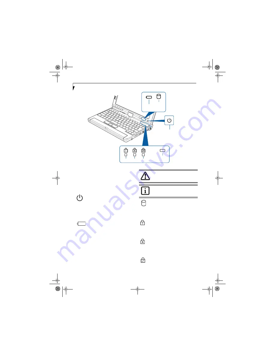
Figure 2-9. Status Indicators

Status Indicators

The status indicators display symbols that correspond to 
specific components of your notebook. 

(Figure 2-9)

 The 

symbols show how each of those components is oper-
ating. Note that keyboard-related indicators (CapsLk, 
NumLk, ScrLk) are located above the keyboard.

POWER INDICATOR

The Power indicator symbol located on the power 
button shows whether your system is operational. When 
it is lit blue, it means that there is power to your 
computer and that it is ready for use.

BATTERY LEVEL INDICATOR

The Battery Level indicators shows whether the Lithium 
ion battery is installed and charging, and how much 
charge is available within the batteries. 

Green:

 The battery is installed and fully charged.

Amber:

 The battery is installed and is approximately 

half charged.

Red: 

The battery charge is low and it should be 

charged with an adapter or replaced with a charged 
battery.

HARD DRIVE ACCESS INDICATOR

The Hard Drive Access indicator lights green when your 
internal hard drive is being accessed.

NUMLK INDICATOR

The NumLk indicator shows that the integral keyboard 
is set in ten-key numeric keypad mode. 

CAPSLOCK INDICATOR

The CapsLock indicator shows that your keyboard is set 
to type in all capital letters. 

SCRLK INDICATOR

The ScrLk indicator shows that your scroll lock is active. 

Battery 

Hard 

NumLk

ScrLk

CapsLk

AC Adapter/
Charging

Level

Drive 
Access

Power Indicator

Batteries subjected to shocks, vibration or 
extreme temperatures can be permanently 
damaged.

If there is no battery activity and the 
power adapters are not connected, the 
Battery Level indicators will also be off.

P Series.book  Page 14  Monday, October 9, 2006  10:58 AM

Содержание P1610 - LifeBook - Core Solo 1.2 GHz

Страница 1: ...Fujitsu LifeBook P1610 Notebook User s Guide P Series book Page 1 Monday October 9 2006 10 58 AM ...

Страница 2: ...P Series book Page 2 Monday October 9 2006 10 58 AM ...

Страница 3: ... ration Bluetooth is a registered trademark of Bluetooth SIG Inc All other trademarks mentioned herein are the property of their respective owners Copyright 2006 Fujitsu Computer Systems Corpora tion All rights reserved No part of this publication may be copied reproduced or translated without prior written consent of Fujitsu Computer Systems Corpora tion No part of this publication may be stored ...

Страница 4: ...in a fire They may explode Check with local codes for possible special disposal instructions To reduce the risk of fire use only No 26 AWG or larger UL Listed or CSA Certified Telecommunica tion Line Cord For TV Tuner Models To protect from overvoltages and transients on the Cable Distribution System make sure that the outer shield of the coaxial cable is con nected to earth grounded at the buildi...

Страница 5: ...t 15 Adjusting Display Panel Brightness 16 Keyboard Using the Keyboard 17 Numeric Keypad 17 Windows Keys 17 Cursor Keys 17 Function Keys 18 LifeBook Security Application Panel Setting up Your LifeBook Security Panel 19 Passwords 19 Operating Your Security Application Panel 20 Precautions 20 Uninstalling the Security Panel Application 20 Using the Lifebook Application Panel 21 Changing Button Funct...

Страница 6: ...king Port 47 Universal Serial Bus Ports 47 Microphone Jack 47 Headphone Jack 47 External Video Port 48 5 TROUBLESHOOTING Troubleshooting Identifying the Problem 51 Specific Problems 51 Troubleshooting Table 52 Power On Self Test Messages 58 Modem Result Codes 59 Restoring Pre installed Software Restoring the Factory Image 60 Automatically Downloading Driver Updates 61 6 CARING FOR YOUR LIFEBOOK Ca...

Страница 7: ...90 Connection to the network 91 Troubleshooting the WLAN Troubleshooting 95 Wireless LAN Glossary Glossary 96 IP address information About IP Addresses 98 WLAN Specifications Specifications 99 Using the Bluetooth Device What is Bluetooth 100 Where to Find Information About Bluetooth 100 APPENDIX B USING THE FINGERPRINT SWIPE SENSOR Fingerprint Sensor Device Introducing the Fingerprint Sensor Devic...

Страница 8: ...L i f e B o o k P 1 6 0 0 S e r i e s N o t e b o o k P Series book Page 8 Monday October 9 2006 10 58 AM ...

Страница 9: ...1 1 Preface P Series book Page 1 Monday October 9 2006 10 58 AM ...

Страница 10: ...2 L i f e B o o k P 1 6 0 0 S e r i e s N o t e b o o k P Series book Page 2 Monday October 9 2006 10 58 AM ...

Страница 11: ...lace the call you should have the following information ready so that the customer support representative can provide you with the fastest possible solution Product name Product configuration number Product serial number Purchase date Conditions under which the problem occurred Any error messages that have occurred Type of device connected if any Fujitsu Online You can go to the online Fujitsu Pro...

Страница 12: ...4 L i f e B o o k P 1 6 0 0 S e r i e s N o t e b o o k P Series book Page 4 Monday October 9 2006 10 58 AM ...

Страница 13: ...5 2 Getting to Know Your LifeBook P Series book Page 5 Monday October 9 2006 10 58 AM ...

Страница 14: ...6 L i f e B o o k P 1 6 0 0 S e r i e s N o t e b o o k P Series book Page 6 Monday October 9 2006 10 58 AM ...

Страница 15: ...er s Guide this document International Limited Warranty Booklet Certificate of Authenticity Lithium ion battery pre installed You may also have one or more of the following devices in the box depending upon the configuration of your system Port Replicator Figure 2 3 External USB Floppy Disk Drive Additional battery s Application CD s for third party software Figure 2 2 AC Adapter Figure 2 3 Option...

Страница 16: ...he internal microphone Fingerprint Sensor Use the fingerprint sensor to log onto the system using your fingerprint as the password Headphone Jack Connect stereo headphones or powered external speakers The internal speaker is disabled when you plug in external headphones or powered speakers Modem Connect a telephone line to the internal modem using a standard RJ 11 telephone plug PCMCIA Card slot I...

Страница 17: ...e 14 Keyboard A full function keyboard with dedicated Windows keys See Keyboard on page 17 Quick Point Pointing Device The Quick Point pointing device consists of two mouse like buttons one scroll button and a cursor control button located near the center of the keyboard See Quick Point Pointing Device Touch Screen on page 24 Speaker The speaker allows you to listen to sound from your system LifeB...

Страница 18: ...re 2 5 WLAN Bluetooth On Off Switch The wireless LAN Bluetooth On Off Switch is used to power off the wireless devices when not in use PC Card Slot The PC Card Slot allows you to insert a PCMCIA Card The PC Card Eject Button is used when ejecting a PC Card from the slot See Inserting PC Cards on page 44 PC Card Slot PC Card Eject Button WLAN Bluetooth On Off Switch P Series book Page 10 Monday Oct...

Страница 19: ...red external speakers See Headphone Jack on page 47 Microphone Jack The microphone jack allows you to connect an external mono microphone See Microphone Jack on page 47 DC Power Jack The DC power jack allows you to plug in the AC adapter or the optional Auto Airline adapter to power your system and charge the internal Lithium ion Battery USB 2 0 Ports The USB 2 0 ports allow you to connect Univers...

Страница 20: ...deo Port behind cover LAN RJ 45 Port Modem Air Vents Anti theft RJ 11 Port Lock Slot The internal multinational modem is not intended for use with Digital PBX systems Do not connect the internal modem to a Digital PBX as it may cause serious damage to the internal modem or your entire LifeBook P1600 Series notebook Consult your PBX manufacturer s documentation for details Some hotels have Digital ...

Страница 21: ...ng overall perfor mance See Memory Upgrade Module on page 41 Port Replicator Connector This connector allows you to connect the optional port replicator Main Unit and Configuration Label The configuration label shows the model number and other information about your LifeBook P1600 Series notebook In addition the configuration portion of the label has the serial number and manufacturer informa tion...

Страница 22: ... installed and fully charged Amber The battery is installed and is approximately half charged Red The battery charge is low and it should be charged with an adapter or replaced with a charged battery HARD DRIVE ACCESS INDICATOR The Hard Drive Access indicator lights green when your internal hard drive is being accessed NUMLK INDICATOR The NumLk indicator shows that the integral keyboard is set in ...

Страница 23: ... the top edge of the display panel pull it forward until it is lying nearly atop the keyboard 4 Push the latch towards the display See A in Figure 2 11 The latch will click twice and the top latch disappears and the bottom latch appears See B in Figure 2 11 Lay the display flush against the system so that the latch rests in the slot in the battery pack You can now use the system as a tablet Figure...

Страница 24: ...just Brightness Windows XP Pro To adjust brightness with the power management utility click Start Control Panel Brightness Control Set the screen brightness slider for battery and AC power scenarios Windows XP Tablet PC Edition To adjust brightness with the Tablet and Pen Settings utility click Start Control Panel Tablet and Pen Settings then select the Display tab Using the Fujitsu Menu to Adjust...

Страница 25: ...nctions as both standard character keys and numeric keypad keys NumLk can be activated by pressing the NumLk key Turning off the NumLk feature is done the same way Once this feature is activated you can enter numerals 0 through 9 perform addition subtraction multiplication or division and enter decimal points using the keys designated as ten key function keys The keys in the numeric keypad are mar...

Страница 26: ...ompensation Video compensation controls spacing on the display When it is enabled displays with less than 1024 x 600 or 800 x 600 pixel resolution will still cover the entire screen Fn F6 Pressing F6 repeatedly while holding Fn will lower the brightness of your display Note that adjusting the brightness using the keyboard changes the system setting Fn F7 Pressing F7 repeatedly while holding Fn wil...

Страница 27: ...otebooks in a working group office or company to allow for system management Individual LifeBook notebooks in a group environment should not use a common password A password consists of one to five button strokes plus the enter button A valid stroke consists of pushing one or up to four buttons simulta neously The following are valid button strokes Pushing 4 by itself Pushing 2 and 3 at the same t...

Страница 28: ... the Suspend Resume button then enter a correct password PRECAUTIONS Opening and Closing the Cover Closing the cover automatically places the notebook into Standby mode Opening the cover does not automati cally place the notebook into normal operation Instead you must enter the proper security password after pushing the Suspend Resume button Low Battery Operations If your LifeBook notebook has low...

Страница 29: ... When calling please have a valid credit card and provide proof of ownership You will then be given instructions on where to ship your notebook USING THE LIFEBOOK APPLICATION PANEL Five application buttons are located on the bottom left hand side of the display and when it is configured to be used as a notebook Figure 2 17 One additional button is located on the right hand side of the displayadjac...

Страница 30: ...ured Backlight On Off Application C Button When you press the Backlight On Off button when the system is running each press of the button will toggle the backlight on and off This is designed as a power saving feature for use when the backlight is not required When you press the Fn button while you press then release the Backlight On Off Application C button you will automatically start whichever ...

Страница 31: ...ange from the list 3 Click Change and open the drop down list in the Action field 4 Select the action you would like the button to perform If you want to launch a program click on Launch an Application then browse to the location of the program 5 Click OK then click OK again The buttons will now perform the actions you have assigned to them Windows XP Tablet PC Edition 1 Double click on the Tablet...

Страница 32: ... Clicking means pushing and releasing a button To left click move the cursor to the item you wish to select press the left button once and then immediately release it Figure 2 19 To right click move the cursor to the item you wish to select press the bottom button once and then immediately release it Figure 2 19 Clicking DOUBLE CLICKING Double clicking means pushing and releasing the left button t...

Страница 33: ...n lift the stylus tip immediately You also have the option to perform the left click operation by tapping lightly with your finger on the Touch Screen once Figure 2 23 Right Clicking Windows XP Professional To right click go to Start Control Panel Touch Panel From the Right Button Simulation tab you can specify a right button tool by using the selected button prior to the desired right mouse click...

Страница 34: ...tion Double click the Tablet and Pen Settings icon and select the Settings tab 3 Windows XP Professional Press the Calibrate Now button Windows XP Tablet PC Edition Click the Calibrate button 4 Adjust the display of your notebook to a comfortable angle and find the symbol in the upper left corner of the display 5 Using the stylus firmly touch the screen directly on the symbol Lift the stylus from ...

Страница 35: ...ny volume controls that are set within individual applications Certain external audio devices you might connect to your system may have hardware volume controls Each source discussed above puts an upper limit on the volume level that must then be followed by the other sources We recommend that you experiment with the various volume controls to discover the optimal sound level Any software that con...

Страница 36: ...28 L i f e B o o k P 1 6 0 0 S e r i e s N o t e b o o k P Series book Page 28 Monday October 9 2006 10 58 AM ...

Страница 37: ...29 3 Using Your LifeBook P Series book Page 29 Monday October 9 2006 10 58 AM ...

Страница 38: ...30 L i f e B o o k P 1 6 0 0 S e r i e s N o t e b o o k P Series book Page 30 Monday October 9 2006 10 58 AM ...

Страница 39: ...Optional Auto Airline Adapter 1 Plug the DC output cable into the DC power jack on your notebook 2 Plug the Auto Airline adapter into the cigarette lighter of an automobile with the ignition key in the On or Accessories position OR 3 Plug the Auto Airline adapter into the DC power jack on an airplane seat Switching from AC Adapter Power or the Auto Airline Adapter to Battery Power 1 Be sure that y...

Страница 40: ... executed when You turn on the power to your notebook You restart your notebook from the Windows Shut Down dialog box The software initiates a system restart e g when you install a new application BIOS SETUP UTILITY The BIOS Setup Utility is a program that sets up the operating environment for your notebook Your BIOS is set at the factory for normal operating conditions there fore there is no need...

Страница 41: ...ble you will be advised on how to select and change an available connection at a later date You will then be asked if you want to register with Microsoft If you are not connected to a phone line and plan to register at a later time you may click the Skip button Once you are connected to the Internet you will be asked if you wish to continue with the registration If you select Yes you will then ent...

Страница 42: ... visible at all the power is off or your system is in Hibernate mode See Hibernate Mode STANDBY MODE Standby mode in Windows saves the contents of your notebook s system memory during periods of inactivity by maintaining power to critical parts This mode will turn off the CPU the display the hard drive and all of the other internal components except those necessary to maintain system memory and al...

Страница 43: ...ess the hard drive will cause it to restart automatically This feature is independent of the Suspend Resume button and can be enabled and disabled in Windows WINDOWS POWER MANAGEMENT The Power Options icon located in the Windows Control Panel allows you to configure some of the power management settings For example you can use the Power Options to set the timeout values for turning off the display...

Страница 44: ...the correct procedure to shut down from Windows allows your notebook to complete its opera tions and turn off power in the proper sequence to avoid errors The proper sequence is 1 Click the Start button and then click Turn Off Computer 2 Select the Turn Off option from within the window If you are going to store your notebook for a month or more see the Care and Maintenance section Turning off you...

Страница 45: ...37 4 User Installable Features P Series book Page 37 Monday October 9 2006 10 58 AM ...

Страница 46: ...38 L i f e B o o k P 1 6 0 0 S e r i e s N o t e b o o k P Series book Page 38 Monday October 9 2006 10 58 AM ...

Страница 47: ...not respond to the low battery alarm the batteries will continue to discharge until they are too low to operate Your notebook will then go into Standby mode to try and protect your data for as long as possible There is no guarantee that your data will not be lost once the system reaches this point Do not leave a faulty battery in your sys tem It may damage your AC adapter optional Auto Airline ada...

Страница 48: ...eries in your battery compartment follow these easy steps Figure 4 1 1 Have a charged battery ready to install 2 Shut down your system and disconnect the AC adapter 3 Lift the display enough to pull the display latch from the slot 4 Press the battery release latches to open the compartment 5 Remove the battery from the compartment 6 Slide the new battery into the compartment 7 Close the compartmen...

Страница 49: ...odule in a static guarded sleeve 8 Install a new module as outlined in the procedure below 9 Replace the cover 10 Replace the screws Figure 4 3 Removing a Memory Module The system contains components that can be severely damaged by electrostatic discharge ESD To minimize risk to the components observe the following precautions Be sure to power down your system before adding or removing system comp...

Страница 50: ...e You can check the memory capacity by clicking Start Control Panel then double clicking the System icon Select the General tab and check the amount of memory under Computer The amount of memory displayed should be approxi mately the total of all memory modules installed There may be a discrepancy of several megabytes which are allocated for fixed video memory The memory upgrade module is not some...

Страница 51: ... is off while inserting them 2 Make sure there is no card currently in the slot If there is see Removing an SD Card 3 Insert your card into the slot with the product label facing up 4 Push the card firmly into the slot until it is seated in the connector REMOVING AN SD CARD To remove an SD Card first see your SD Card manual for instructions Some cards may require your LifeBook notebook to be in Su...

Страница 52: ...ot firmly until it is seated in the opening REMOVING PC CARDS To remove a PC Card follow these steps 1 See your PC Card manual for specific instructions on removing your card Some PC Cards may require your notebook to be in Standby Mode or Off while removing them 2 Push the Eject button until it pops out and then push it in to eject the card This will allow you to remove the card Eject Button PC C...

Страница 53: ...t Replicator not the one on your system LAN RJ 45 Jack The LAN jack allows you to connect a LAN to the Port Repli cator Note that when the system is attached to the Port Repli cator the LAN Jack on the Port Replicator should be used not the one on the system Docking Port The docking port connects the Port Replicator to your Life Book notebook Port Replicator Release Latch Pull the Port Replicator ...

Страница 54: ...eously Figure 4 8 Figure 4 8 Attaching the Port Replicator DETACHING PORT REPLICATOR To detach the Port Replicator 1 Pull the Port Replicator s release latch away from the Port Replicator to release it from your notebook Figure 4 9 Figure 4 9 Unlatching the Port Replicator 2 Pull the notebook away from the Port Replicator to detach it from your system Figure 4 10 Figure 4 10 Removing the Port Repl...

Страница 55: ...a USB device follow these easy steps See figure 2 7 on page 12 for location 1 Align the connector with the port opening 2 Push the connector into the port until it is seated MICROPHONE JACK The microphone jack allows you to connect an external mono microphone Your microphone must be equipped with a 1 8 3 5 mm mono mini plug in order to fit into the microphone jack of your notebook In order to conn...

Страница 56: ...ted on each side of the connector If you plug headphones into the headphone jack the built in stereo speakers will be disabled When an external monitor is plugged in pressing the Fn F10 keys allows you to change your selection of where to send your display video Each time you press the key combination you will step to the next choice starting with the built in display panel only moving to the exte...

Страница 57: ...49 5 Troubleshooting P Series book Page 49 Monday October 9 2006 10 58 AM ...

Страница 58: ...50 L i f e B o o k P 1 6 0 0 S e r i e s N o t e b o o k P Series book Page 50 Monday October 9 2006 10 58 AM ...

Страница 59: ...pport website at http www computers us fujitsu com support for possible known support issues 9 If you have tried the solutions suggested in the Troubleshooting Table and checked our website for possible solutions without success contact your support representative Toll free 1 800 8Fujitsu E mail 8fujitsu us fujitsu com Website http www computers us fujitsu com support Before you place the call you...

Страница 60: ...ional Port Replicator Port Replicator AC adapter is not plugged in Provide power to the Port Replicator LifeBook is not properly seated in the Port Replicator Remove and re dock your notebook Hard Drive Problems You cannot access your hard drive The setup utility is incorrectly set for your internal Primary Master hard drive Revise BIOS settings to set the Primary Master correctly See BIOS Setup U...

Страница 61: ...oblems Power On screen or Info menu of BIOS setup utility information does not show the correct amount of installed memory Your memory upgrade module is not properly installed Turn off your system Remove and re install your memory upgrade module See Memory Upgrade Module on page 41 You have a memory failure Check for Power On Self Test POST messages See Power On Self Test Messages on page 58 Modem...

Страница 62: ...ort remove that battery and operate from another power source or replace that battery The battery is low Check the Status Indicator Panel to determine the pres ence and condition of the battery See Status Indica tors on page 14 Use a Power adapter until the battery is charged The AC or auto airline adapter is not plugged in properly Verify that your adapter is connected correctly See Power Sources...

Страница 63: ...on when at all possible The power savings features may be disabled Check the power management and or setup utility settings in the Power Savings menu and adjust according to your operating needs The brightness is turned all the way up Turn down the brightness adjustment The higher the brightness the more power your display uses The battery is very old Replace the battery The battery has been expos...

Страница 64: ...when you turn on your note book The angle of the display and the brightness settings are not adequate for your lighting conditions Move the display and the brightness control until you have adequate visibility The optional Port Replicator is attached an external monitor is plugged in and the system is set for an external monitor only Pressing F10 while holding down the Fn key allows you to change ...

Страница 65: ...setting See the Video Features submenu located within the Advanced menu of the BIOS See BIOS Setup Utility on page 32 You have connected an external monitor and it does not display any information Your BIOS setup is not set to enable your external monitor Try toggling the video destination by pressing Fn and F10 together or check your BIOS setup and enable your external monitor See the Video Featu...

Страница 66: ...ems You can continue operating but should contact your support representative for more information Keyboard controller error The keyboard controller test failed You may have to replace your keyboard or keyboard controller but may be able to use an external keyboard until then Contact your support representative Keyboard error Keyboard not working You may have to replace your keyboard or keyboard c...

Страница 67: ...risk corrupting your data Contact your support representative for repairs nnnn System RAM Passed Where nnnn is the amount of system memory in kilobytes successfully tested System timer error The timer test failed The main clock that operates the computer is faulty Requires repair of system board Contact your support representative for repairs UMB upper limit segment address nnnn Displays the addre...

Страница 68: ...stem is set up to boot from the CD drive To verify change the boot up priority rather than booting up from the hard drive or an external floppy disk drive perform the following steps 1 Start your system and press the F2 key when the Fujitsu logo appears You will enter the BIOS Setup Utility 2 Using the arrow keys go to the Boot menu 3 Arrow down to the Boot Device Priority submenu Press Enter 4 If...

Страница 69: ...The FDU icon should appear in the notification area at the bottom right of your screen roll the cursor over the icons to find the correct one If the FDU icon does not appear in the notification area it can be started by going to Start All Programs and clicking on Fujitsu Driver Update this will create the icon automati cally To invoke the FDU menu right click on the FDU icon The menu contains the ...

Страница 70: ...62 L i f e B o o k P S e r i e s N o t e b o o k S e c t i o n F i v e L i f e B o o k P 1 6 0 0 S e r i e s N o t e b o o k P Series book Page 62 Monday October 9 2006 10 58 AM ...

Страница 71: ...63 6 Care and Maintenance P Series book Page 63 Monday October 9 2006 10 58 AM ...

Страница 72: ...64 L i f e B o o k P 1 6 0 0 S e r i e s N o t e b o o k P Series book Page 64 Monday October 9 2006 10 58 AM ...

Страница 73: ...carrying case make sure that there are no objects in the case pressing on the lid Do not drop your notebook Do not touch the screen with any sharp objects Cleaning your LifeBook Always disconnect the power plug Pull the plug not the cord Clean your system with a damp lint free cloth Do not use abrasives or solvents Use a soft cloth to remove dust from the screen Never use glass cleaners Storing yo...

Страница 74: ... or two Intense heat can shorten battery life Do not leave a battery in storage for longer than six months without recharging it Increasing Battery Life Keep brightness to the lowest comfortable level Set the power management for maximum battery life Put your notebook in Standby mode when it is turned on and you are not actually using it Disable the Windows CD auto insert function Always use fully...

Страница 75: ... edge Caring for your Optional Optical Drive Your optical drive is durable but you must treat it with care Please pay attention to the following points The drive rotates the compact disk at a very high speed Do not carry it around or subject it to shock or vibration with the power on Avoid using or storing the drive where it will be exposed to extreme temperatures Avoid using or storing the drive ...

Страница 76: ...68 L i f e B o o k P 1 6 0 0 S e r i e s N o t e b o o k P Series book Page 68 Monday October 9 2006 10 58 AM ...

Страница 77: ...69 7 System Specifications P Series book Page 69 Monday October 9 2006 10 58 AM ...

Страница 78: ...70 L i f e B o o k P 1 6 0 0 S e r i e s N o t e b o o k P Series book Page 70 Monday October 9 2006 10 58 AM ...

Страница 79: ...8 Mb for fingerprint recognition P1600 U1400 8 9 WXGA 512M 60G MODEM LAN WLAN WIN XPP Configuration P N AP8XXXXXXXXXXXXX FPC P N FPCMXXXXXX Model Processor Screen Size Operating System Hard Drive Part Number Configuration ID Memory Communications Hard disk drive 1 8 HDD 30 GB 60 GB or 80 GB IDE 4200 rpm DMA 100 Shock mounted Shock Sensor feature SMART Support Display Specifications Display 8 9 TFT...

Страница 80: ...h max 56 0 WHr Recharge Time Approximately 4 5 hours AC Adapter Autosensing 100 240V supplying 16 VDC with a minimum current of 2 5 A Environmental Specifications Temperature Operating 41o to 95o F 5o to 35o C Non operating 5o to 140o F 15o to 60o C LifeBook P1600 Series notebook Specifications Humidity Operating 20 to 85 non condensing Non operating 8 to 85 non condensing Agency Approval Specific...

Страница 81: ... an incoming call In most but not all areas the sum of RENs should not exceed five 5 0 To be certain of the number of devices that may be connected to a line as determined by the total RENs contact the local tele phone company If this equipment causes harm to the telephone network the telephone company will notify you in advance that temporary discontinuance of service may be required But if advan...

Страница 82: ...te conformité est confirmée par le numéro d enregistrement Le sigle IC placé devant le numéro d enregistrement signifie que l enregistrement s est effectué conformément à une déclaration de conformité et indique que les spécifications techniques d Industrie Canada ont été respectées Il n implique pas qu Industrie Canada a approuvé le matériel Avant de connecter cet équipement à une ligne télépho n...

Страница 83: ...75 8 Glossary P Series book Page 75 Monday October 9 2006 10 58 AM ...

Страница 84: ...76 L i f e B o o k P 1 6 0 0 S e r i e s N o t e b o o k P Series book Page 76 Monday October 9 2006 10 58 AM ...

Страница 85: ...a between the CPU and the sub assemblies inside your notebook Byte 8 bits of parallel binary information Cache Memory A block of memory built into the micro processor which is much faster to access than your system RAM and used in specially structured ways to make your overall data handling time faster CardBus A faster 32 bit version of the PC Card interface which offers performance similar to the...

Страница 86: ...fic brand and model of device in order to produce the desired results from that particular equipment ECP Extended Capability Port A set of standards for high speed data communication and interconnection between electronic devices Encryption Key Network Key Key information used to encode data for data transfer This device uses the same encryption key to encode and decode the data and the identical ...

Страница 87: ...organization which produces standards for communication using infrared as the carrier IRQ Interrupt Request An acronym for the hardware signal to the CPU that an external event has occurred which needs to be processed KB Kilobyte LAN Local Area Network An interconnection of computers and peripherals within a single limited geographic location which can pass programs and data amongst themselves LCD...

Страница 88: ...etwork keys However in case of actual communications the same network key must be set Open system authentication is sometimes called Open key authentication Operating System A group of control programs that convert application commands including driver programs into the exact form required by a specific brand and model of micro processor in order to produce the desired results from that particular...

Страница 89: ...er time If a failure is likely to occur SMART makes a status report available so that the notebook can prompt the user to back up the data on the drive Naturally not all failures are predictable SMART predictability is limited to those attributes which the drive can self monitor In those cases where SMART can give advance warning a considerable amount of precious data can be saved SRAM Static rand...

Страница 90: ...t the product has passed the interoperability test supplied by the WECA Wireless Ethernet Compatibility Alliance which guar antees the interoperability of wireless IEEE 802 11 LAN products For more information on the Wi Fi standard go to the WECA website at www wirelessethernet com WLAN Wireless Local Area Network A wireless interconnection of computers and peripherals within a single limited geog...

Страница 91: ...83 Appendix A Integrated Wireless LAN User s Guide Optional Device P Series book Page 83 Monday October 9 2006 10 58 AM ...

Страница 92: ...84 L i f e B o o k P 1 6 0 0 S e r i e s N o t e b o o k P Series book Page 84 Monday October 9 2006 10 58 AM ...

Страница 93: ...ce with the instructions it may cause harmful interference to radio communications However there is no guarantee that interference will not occur in a particular installa tion If this equipment does cause harmful interference to radio or televi sion reception which can be determined by turning the equipment off and on the user is encouraged to try and correct the interference by one or more of the...

Страница 94: ...ss 2915ABG and Atheros AR5002X WLAN devices are capable of three operat ing modes IEEE 802 11a IEEE 802 11b and IEEE 802 11g Encoding of data is modulated using Direct Sequence Spread Spectrum DSSS and Complementary Code Keying CCK when the WLAN device is operating in IEEE 802 11b mode and Orthogonal Frequency Divi sion Multiplexing OFDM when operating in IEEE 802 11a or IEEE 802 11g mode The WLAN...

Страница 95: ...fere with the operation of WLAN device as microwave ovens operate in the same 2 4GHz frequency range that IEEE 802 11b g devices operate in Interference by microwaves does not occur with IEEE 802 11a radio which operates in the 5 GHz RF band Wireless devices that transmit in the 2 4GHz fre quency range may interfere with the operation of WLAN devices in IEEE 802 11b g modes Symptoms of interferenc...

Страница 96: ...2 Select Intel ProSet Wireless then click on Intel ProSet Wireless from the menu that appears The Intel ProSet Wireless utility will be displayed 3 At the bottom left corner of the window select Wireless Off from the dropdown list Deactivation using Atheros Client Utility software 1 Right click on Atheros Client Utility icon in the system tray Select Open Atheros Client Utility from the menu 2 Cho...

Страница 97: ...as the SSID Network Key WEP Required if using static WEP keys Authentication Type Open Shared WPA or WPA PSK Procedure 1 Activate the WLAN device using either the Wireless On Off Switch or the Intel PROSet software 2 Click the Start button first and then All Pro grams 3 Click the icon Intel PROSet Wireless to execute the Intel PROSet Wireless software 4 Click the Add button The General Settings di...

Страница 98: ...ent tab 4 If this is your first time using this utility highlight the profile Default and Click the Modify button otherwise Click the New button The General Set tings dialog displays 5 From the General page enter a profile name in the Profile Name field 6 Enter the network SSID in the SSID1 field If you wish to create a profile that can connect to up to 3 different wireless networks SSID s can be ...

Страница 99: ...ss automatically If your network uses static IP addresses consult with your network adminis trator for the correct IP address settings 8 Click the OK button Processing will return to the Wireless Network Connection Properties window 9 Click the OK button 10 Close the Network Connection window Following this operation confirm the names of the computer and the workgroup as follows Confirming the com...

Страница 100: ...enu dis played The Wireless Network Connection Proper ties window will be displayed 5 If File and Printer Sharing for Microsoft Net works is displayed proceed to step 6 If File and Printer Sharing for Microsoft Networks is not dis played skip to step 7 6 Make sure that the File and Printer Sharing for Microsoft Networks check box is checked and then click the OK button Skip to Setting file sharing...

Страница 101: ...will be displayed 5 Double click the folder to be accessed Confirming the status of the radio 1 Right click the Intel PRO Wireless icon in the lower right corner of the screen 2 Click Open Intel PROSet for Wireless The Intel PROSet for Wireless window opens 3 Contained within the General tab and the Details section accessed by pressing the Details button you will find the current operating status ...

Страница 102: ...io Frequency Channel Number Network Authentication Data Encryption 802 1x Authentication Type 802 1x Authentication Protocol CCX Version CCX TPC CCX Power Levels Access Point MAC Address Mandatory Access Point P Series book Page 94 Monday October 9 2006 10 58 AM ...

Страница 103: ...lowing page Confirming the status of the radio waves on page 93 The WLAN device has been deactivated or disabled Check if the wireless switch is turned ON Also verify Disable Radio is not checked in Network setting window Refer to Activating the Wireless LAN on page 88 The computer to be connected is turned off Check if the computer to be connected is turned ON RF interference from Access Points o...

Страница 104: ...nternet Protocol that uniquely identifies a computer on a network The IP address is usually expressed in dotted decimal notation LAN Local Area Network A LAN or Local Area Network is a computer network or data communications network which is confined to a limited geographical area MAC address Media Access Control Address A MAC address also called an Ethernet address or IEEE MAC address is the 48 b...

Страница 105: ...ile device tries to connect to the BSS The SSID differentiates one WLAN from another so all access points and all devices attempting to connect to a specific WLAN must use the same SSID A device will not be permitted to join the BSS unless it can provide the unique SSID Because the SSID is broadcast in plain text it does not supply any security to the network Subnet mask TCP IP network is controll...

Страница 106: ...expressed with four values in the range between 1 and 255 Set the each computer as follows The value in paren theses is a subnet mask Example Computer A 192 168 100 2 255 255 255 0 Computer B 192 168 100 3 255 255 255 0 Computer C 192 168 100 4 255 255 255 0 Computer X 192 168 100 254 255 255 255 0 IP addressing is much more complicated than can be briefly explained in this document You are advise...

Страница 107: ...B6 and the Intel PRO Wireless 3945ABG WM3945ABG Network Connections WLAN devices conform to IEEE 802 11a and 802 11b g Wi Fi based Transfer rate Automatic switching IEEE 802 11a g 54 Mbps maximum data rate IEEE 802 11b 11 Mbps maximum data rate Active frequency 802 11b g 2400 2473 MHz 802 11a 5050 5850 MHz Number of channels 802 11a 8 independent channels 802 11b g 11 channels 3 non overlapping ch...

Страница 108: ...the Help file click Start All Programs and click on Toshiba Select Bluetooth then select User s Guide For additional information about Bluetooth Technology visit the Bluetooth website at www bluetooth com Canadian Notice To prevent radio interference to the licensed service this device is intended to be operated indoors and away from windows to provide maximum shielding Equipment or its transmit a...

Страница 109: ...101 Appendix B Using the Fingerprint Swipe Sensor P Series book Page 101 Monday October 9 2006 10 58 AM ...

Страница 110: ...102 L i f e B o o k P 1 6 0 0 S e r i e s N o t e b o o k P Series book Page 102 Monday October 9 2006 10 58 AM ...

Страница 111: ...lled by checking to see if the following are present The presence of the gold key shaped OmniPass icon in the system tray at the bottom right of the screen The presence of the Softex program group in the Programs group of the Start menu System Requirements The OmniPass application requires space on your hard drive it also requires specific Operating Systems SO s The minimum requirements are as fol...

Страница 112: ...req14 He then goes to his webmail site to log onto his account He inputs his webmail credentials as usual username John_02 and password tablet but instead of clicking Submit he directs OmniPass to Remember Password Now whenever he returns to that site OmniPass will prompt him to supply access credentials John enters his OmniPass user credentials John_01 and freq14 in the OmniPass authentication pr...

Страница 113: ...ce capturing your fingerprint When you are comfortable with how your fingerprint is captured proceed to enroll a finger 3 Once OmniPass has successfully acquired the finger print the Verify Fingerprint screen will automati cally appear To verify your enrolled fingerprint place your fingertip on the sensor and hold it there as if you were having a fingerprint captured Successful fingerprint verific...

Страница 114: ... authentication settings Settings for this Pass word Site can always be changed in Vault Management Logging in to a Remembered Site Whether or not OmniPass prompts you to authenticate when you return to a remembered site is determined by Settings for this Password Site and can be changed in Vault Management The following cases are applicable to using OmniPass to login to Windows remembered website...

Страница 115: ...n choose the identity with which you are logging in if you login using master password Choosing User Identity during Login To choose your identity during login type your user name in the User Name field Press Tab and see that the Domain field self populates Click the Password field to bring the cursor to it and you will see the pull down menu in the Identity field Select the identity you wish to l...

Страница 116: ...the username Tom and the password Sun shine I can now successfully import the OmniPass user data to the new system If you export an OmniPass only user you can import that user to any computer running OmniPass pro vided that a user with that name is not already enrolled in OmniPass If you attempt to import a user profile who has the same name as a user already enrolled in OmniPass the OmniPass impo...

Страница 117: ... using the same username and password Cannot add Windows users to OmniPass If you experience difficulties adding a Windows user to OmniPass you may need to adjust your local secu rity settings You can do this by going to Start Control Panel Administrative Tools and Local Security Settings Expand Local Policies expand Security Options and double click Network Access Sharing and Security Model for L...

Страница 118: ...110 L i f e B o o k P 1 6 0 0 S e r i e s N o t e b o o k P Series book Page 110 Monday October 9 2006 10 58 AM ...

Страница 119: ...lick Me 33 Closed Cover Switch 9 Configuration Label 13 Conventions used 3 Cursor Keys 17 D DC in connector 8 DC Power Jack 11 31 Device Ports 47 DIMM 41 Display Panel 9 brightness 16 latch 9 opening 15 problems 56 57 Display Timeout 35 Docking Port 47 Drivers and Application Restore CD 60 E Error Messages 58 External Monitor Port 12 48 F FDU 61 Fingerprint Sensor Device 103 Configuring OmniPass 1...

Страница 120: ...ing 20 Local Area Network LAN 8 M Memory capacity 42 compartment 13 42 installing 41 problems 53 removing 42 upgrade module 41 Memory Stick installing 43 Microphone Jack 8 47 Microprocessor 71 modem 8 12 53 Modem RJ 11 Port 12 Modem Jack 47 Modem Result Codes 59 Mouse 52 53 N Numeric Keypad 17 NumLk Indicator 14 O optional accessories 7 P PC Card care 67 installing 44 problems 54 removing 44 slot ...

Страница 121: ...e keyboard 52 PC Card 54 port replicator 52 ports 53 54 power 54 video 56 U Universal Serial Bus Port 47 USB 47 problems 53 54 USB 2 0 ports 12 USB port 8 Using the system as a Tablet 15 V volume control 27 W Windows keys 17 Application key 17 Start key 17 Wireless LAN access point infrastructure mode 87 activating the WLAN device 88 ad hoc mode 86 before using the wireless LAN 86 configuration 89...

Страница 122: ...114 L i f e B o o k P S e r i e s N o t e b o o k I n d e x L i f e B o o k P 1 6 0 0 S e r i e s N o t e b o o k P Series book Page 114 Monday October 9 2006 10 58 AM ...

Страница 123: ...P Series book Page 115 Monday October 9 2006 10 58 AM ...

Страница 124: ...P Series book Page 116 Monday October 9 2006 10 58 AM ...

Страница 125: ...P Series book Page 117 Monday October 9 2006 10 58 AM ...

Страница 126: ...P Series book Page 118 Monday October 9 2006 10 58 AM ...

Страница 127: ...P Series book Page 119 Monday October 9 2006 10 58 AM ...

Страница 128: ...P Series book Page 120 Monday October 9 2006 10 58 AM ...

Отзывы: