background image

C141-E054-02EN

1 - 33

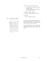
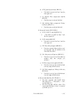
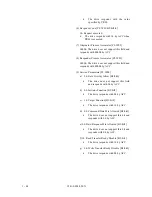
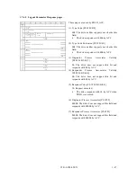
(6) SEQ_ID.. (Sequence Identifier)

• 

The drive does not check this item.

• 

The drive responds with FFh.

(7) DF_CTL.. (Data Field Control)

Set 00h because no optional header is used.

(8) SEQ_CNT.. (Sequence Count)

• 

The drive does not check this item.

• 

The drive responds with 0000h.

(9) OX_ID.. (Originator Exchange Identifier)

• 

The drive responds with OX_ID received
from the initiator.

(10) RX_ID.. (Responder Identifier)

Set FFFFh to indicate that RX_ID is unused.

(11) Parameter

Unused in the Extended Link Service.

Содержание MAA3182FC Series

Страница 1: ...C141 E054 02EN MAA3182FC SERIES MAF3364FC SERIES MAG3091FC MAG3182FC SERIES DISK DRIVES FIBRE CHANNEL INTERFACE SPECIFICATIONS ...

Страница 2: ...y Use the product according to this manual Functional Limitations There may be certain functional limitations concerning the specifications and functions of the products covered by this manual depending on the equipment version especially concerning the following functions Versions in which there functions can be used will be communicated through ENGINEERING CHANGE REQUEST NOTICE issued by Fujitsu...

Страница 3: ...e ANSI ANSI X3 230 1994 FIBRE CHANNEL PHYSICAL AND SIGNALING INTERFACE FC PH American National Standards Institute ANSI ANSI X3 297 1996 FIBRE CHANNEL PHYSICAL AND SIGNALING INTERFACE 2 FC PH 2 American National Standards Institute ANSI ANSI X3 272 199x FIBRE CHANNEL ARBITRATED LOOP FC AL American National Standards Institute ANSI ANSI X3 269 199x FIBRE CHANNEL PROTOCOL FOR SCSI SCSI FCP American ...

Страница 4: ...ON RECORD Edition Date published Revised contents 01 April 1998 02 May 1999 Specification No C141 E054 EN The contents of this manual is subject to change without prior notice All Rights Reserved Copyright 1999 FUJITSU LIMITED ...

Страница 5: ...This page is intentionally left blank ...

Страница 6: ...apters shown below a glossary and a list of abbreviations Chapter 1 Fibre Channel Interface This chapter describes the topology physical and electrical requirements interface protocol and other operations of the Fibre channel FC interface which connects the MAA31xxFC MAF33xxFC MAG3xxxFC Chapter 2 Command Processing This chapter describes the basic logical specifications related to Fibre channel pr...

Страница 7: ...ese disk drives are called Intelligent Disk Drive IDD drive or device in this manual Note 1 Model Name M AF 3 364 FC Interface type FC Fibre Channel Formatted capacity 100 MB units Disk size 3 3 5 inch Type AA 1 6 inch height 7 200 rpm AF 1 6 inch height 10 000 rpm AG 1 inch height 10 000 rpm Warning Indications The following warning indications are shown in this manual to prevent the user and oth...

Страница 8: ...nts Please use the User s Comment Form attached to the end of this manual to identify user comments including error inaccurate and misleading information of this manual Contact to your Fujitsu representative for additional comment forms if required ...

Страница 9: ...viii C141 E054 02EN This page is intentionally left blank ...

Страница 10: ...nance Interface Specifications This Manual 1 Fibre Channel Interface 2 Command Processing 3 Data Buffer Management 4 Command Specifications 5 Sense Data and Error Recovery Methods 6 Disk Media Management Maintenance Manual 1 Specifications and Equipment Configuration 2 Maintenance and Diagnosis 3 Troubleshooting 4 Removal and Replacement Procedures 5 Operating Theory ...

Страница 11: ...This page is intentionally left blank ...

Страница 12: ...Chapter 17 1 7 1 3 Physical Requirements Electrical Requirements 1 10 1 3 1 Interface connector 1 10 1 3 2 Signal function in SFF8045 mode 1 12 1 3 3 Signal function in SFF8067 mode 1 17 1 4 Drive Operation on the Loop 1 18 1 4 1 Loop Initialization 1 18 1 4 2 Arbitration 1 23 1 4 3 Communication between Initiator and Target 1 24 1 5 Ordered Sets Refer to FC PH Section 11 4 and FC AL Chapter 6 1 2...

Страница 13: ...1 7 10 Link Service Reject LS_RJT 1 54 1 8 Extended Link Service Loop Initialization 1 56 1 8 1 Loop Initialization Select Master LISM 1 57 1 8 2 Assign AL_PA frame LIFA LIPA LIHA LISA 1 58 1 8 3 Position Map Information LIRP LILP 1 59 1 9 FC 4 Device Data 1 60 1 9 1 FCP CMND 1 60 1 9 1 1 Control Field FCP_CNTL 1 62 1 9 1 2 Command Descriptor Block 1 63 1 9 2 FCP XFER RDY 1 64 1 9 3 FCP DATA 1 66 ...

Страница 14: ...ition multiple hold 2 18 2 6 Sense Data Hold State 2 19 2 7 Command Processing Exceptions 2 19 2 7 1 Overlapping commands 2 19 2 7 2 Illegal LUN specification 2 20 2 7 3 Reserved operation code 2 20 2 7 4 Command processing in the not ready state 2 20 2 7 5 Error recovery processing 2 22 2 7 6 Reset processing 2 23 2 7 7 Fatal hardware errors 2 26 2 8 Data Block Addressing 2 27 2 8 1 Definition of...

Страница 15: ...OP UNIT 1B 4 71 4 1 10 RESERVE 16 4 73 4 1 11 RESERVE EXTENDED 56 4 75 4 1 12 RELEASE 17 4 77 4 1 13 RELEASE EXTENDED 57 4 78 4 1 14 REQUEST SENSE 03 4 79 4 2 Data Access Commands 4 81 4 2 1 READ 08 4 81 4 2 2 READ EXTENDED 28 4 82 4 2 3 WRITE 0A 4 83 4 2 4 WRITE EXTENDED 2A 4 85 4 2 5 WRITE AND VERIFY 2E 4 86 4 2 6 VERIFY 2F 4 87 4 2 7 SEEK 0B 4 89 4 2 8 SEEK EXTENDED 2B 4 90 4 2 9 SYNCHRONIZE CA...

Страница 16: ...is and error recovery methods 5 10 5 2 2 Sense data analysis and error recovery methods 5 12 5 2 3 Error logging 5 19 5 3 Disk Drive Error Recovery Processing 5 20 5 3 1 Error states and retry processing procedures 5 20 5 3 2 Auto alternate block allocation processing 5 21 5 3 3 Error recovery processing control 5 22 CHAPTER 6 DISK MEDIA MANAGEMENT 6 1 6 1 Defect Management 6 1 6 2 Disk Media Init...

Страница 17: ...1 16 Read Data Transfer 1 25 1 17 Data Transfer Protocol 1 75 1 18 Discovery DISCOV process flow 1 76 1 19 COMMAND WRITE phase 1 77 1 20 Byte Bit alignment in ESI 1 78 1 21 READ phase 1 78 1 22 Public Loop Configuration 1 79 1 23 General Public Loop Initialization sequence 1 80 2 1 6 Byte CDB Basic Format 2 2 2 2 10 Byte CDB Basic Format 2 2 2 3 Supported Status Bytes 2 6 2 4 General read data tra...

Страница 18: ...ching parameters 4 43 4 14 MODE SELECT parameters control mode parameters 4 48 4 15 MODE SELECT parameters additional error recovery parameters 4 59 4 16 MODE SELECT EXTENDED command Group 2 parameter configuration 4 62 4 17 MODE SENSE command Group 0 parameter configuration 4 66 4 18 MODE SENSE EXTENDED command Group 2 parameter configuration 4 70 4 19 FORMAT UNIT command parameter list configura...

Страница 19: ...4 31 READ BUFFER command buffer data Mode 000 001 4 128 4 32 READ BUFFER command buffer descriptor 4 130 5 1 Expanded sense data format 5 2 5 2 Sense key inherent information 5 4 5 3 Analysis of the termination status 5 10 ...

Страница 20: ...ification 1 32 1 16 Detail errors and action 1 73 1 17 Actions by recipient 1 74 1 18 COMMAND bytes definition 1 77 1 19 ASC ASCQ defined for ESI conditions 1 78 1 20 Transmitting and receiving of frames at the interface 1 80 2 1 Sense data in not ready state 2 21 2 2 Outline of disk drive error recovery processing 2 23 2 3 Comparison between FC and SCSI about definition 2 23 2 4 Reset processing ...

Страница 21: ...This page is intentionally left blank ...

Страница 22: ...red Sets Refer to FC PH Section 11 4 and FC AL Chapter 6 1 6 Basic Link Service 1 7 Extended Link Service 1 8 Extended Link Service Loop initialization 1 9 FC 4 Device Data 1 10 Errors on Loop Refer to FP PH Section 29 9 1 11 Enclosure Service Interface ESI 1 12 Public Loop 1 13 Dual Loop This chapter describes the topology physical and electrical requirements interface protocol and operation of t...

Страница 23: ... where Node mean the Target or initiator Each Loop signal is transmitted by one way direction and made of electrical wires called link Each node is connected to the loop vial the port which the node owns Each port consists of the receiver which receives information from the loop and the transmitter which sends information In this example each node has two ports building two independent loops Infor...

Страница 24: ...e loop has no FL_port for fabric loop and all nodes are NL_ports If there is a FL_port which is managing the loop the loop is called a public This can connect up to 126 active NL_port and one FL_port to the same loop And the NL_ports use arbitration to establish a Initiator Target connections See Figure 1 1 1 1 4 Port Bypass Circuit BC Port bypass circuit is to bypass the drive if it cannot provid...

Страница 25: ...led 8B 10B encoding And to prevent too many same signal ones or zeros 10 bit character has an option to balance total numbers of ones or zeros This balancing is called running disparity 1 1 6 Buffer to buffer frame transfer As shown in Figure 1 3 data transmission occurs from an output buffer in the node part to an input buffer in the node port The basic unit of buffer to buffer transfer is the fr...

Страница 26: ... address of source and destination frame control information and user protocol SCSI Command data and etc information Table 1 1 shows category of the data on the loop Table 1 1 Data category on the Loop Data Example Ordered Sets Frame Delimiters Primitive Signals Primitive Sequence SOF EOF Idle R_RDY OPN CLS LIP LPE LPB Frame Link Data Basic Link Service Extended Link Service FC 4 Device Data Comma...

Страница 27: ...d the function of Primitive Signals is below a Idle to indicate the port can transmit or receive the frame b R_RDY to indicate the port has an area for receiving the frame c ARBx to request the right to use the loop x AL_PA of the requesting port d ARB FO to request the right lowest priority to use the loop e OPN to inform the transmission of the frame to the destination port f CLS to inform the r...

Страница 28: ...rame protocol F_CTL Frame Control information SEQ_ID Sequence Identifier uniquely identifies frames in a non streamed sequence DF_CTL Data Field Control specifies the optional headers in the payload This field is not supported by the drive and used as 00h SEQ_CNT Sequence Count identifies the order of the frames OX_ID Originator Exchange Identifier assigned by the originator of an exchange This va...

Страница 29: ...oop Initialization Soft Assigned q Loop Initialization Report Position r Loop Initialization Loop Position PLOGI declare the initiator access the target LOGO declare the initiator finished accessing the target PRLI PRLI is send by the initiator to a target to establish the SCSI FCP operating features PRLO declare the initiator finished accessing the target PDISC issued by the initiator to verify t...

Страница 30: ...I write operation Exchange from command frame to response frame FCP_DATA_IU Write FCP_XFER_RDY_IU FCP_CMND_IU WT 3 2 1 Target drive Initiator FCP_RSP_IU 4 b SCSI read operation Exchange from command frame to response frame FCP_DATA_IU Read FCP_CMND_IU RD 3 1 Target drive Initiator FCP_RSP_IU 4 Figure 1 6 Examples of Exchange 1 FCP_CMND_IU includes SCSI command and the control information 2 FCP_XFE...

Страница 31: ...for the fibre channel loop bus is an unshielded SCA 2 connector conforming to SCSI 3 type which has two 20 pin rows spaced 1 27 mm 0 05 inch apart Figure 1 7 shows the fibre channel connector See Section 1 3 2 1 3 3 for signal assignments on the connector Figure 1 7 SCA2 type interface connector IDD ESD contact ...

Страница 32: ...tive LED out PortB_in 27 08 Spindle sync PortB_in 28 09 Start_1 Mated GND 29 10 Start_2 Mated PortA_out 30 11 EN bypass port B PortA_out 31 12 SEL_6 DSK_WR GND 32 13 SEL_5 DSK_RD PortB out 33 14 SEL_4 ENCL_ACK PortB out 34 15 SEL_3 D 3 GND 35 16 Fault LED out SEL_2 D 2 36 17 N C SEL_1 D 1 37 18 N C SEL_0 D 0 38 19 5V N C 39 20 5V 5V charge 40 Note 1 Signal names in the right column of the table ar...

Страница 33: ...e drive 12V charge 12V 5 12 6 Amps 1 Amps 5V charge 5V 5 17 6 Amps 1 Amps 2 Fault LED out The drive starts and this signal lights when it detects internal failure The Fault LED out signal is an open collector output The LED and the current limiting register are external to the drive See Table 1 5 Table 1 5 Characteristics of Fault LED out signal State Current Output Voltage LED off 100µA IOH 100µA...

Страница 34: ...he drive has been mated to a backplane Table 1 6 Definition of motor start mated control Start_2 Mated Start_1 Mated Function open open ground ground open ground open ground Drive is not mated to a backplane The drive s motor does NOT spin up Drive is mated to a backplane The drive s motor spins up when the drive receives SCSI start command after a mating deskew time has passed Drive is mated to a...

Страница 35: ... tested by the drive when powered on SEL_6 is the most significant bit and SEL_0 is the elast significant bit Electric requirement for the signals is listed in Table 1 8 These signals with high state have approximately 10KΩ register on the backplane Table 1 8 Electric requirement for SEL_n inputs State Current Voltage high 20 µA IIH 20 µA 2 2V VIH 5 25V low 20 µA IIL 20 µA 0 5V VIL 0 7V SEL ID SEL...

Страница 36: ...36 39 61 D3 0C 81 37 36 62 D2 0D 80 38 35 63 D1 0E 7C 39 34 64 CE 0F 7A 3A 33 65 CD 10 79 3B 32 66 CC 11 76 3C 31 67 CB 12 75 3D 2E 68 CA 13 74 3E 2D 69 C9 14 73 3F 2C 6A C7 15 72 40 2B 6B C6 16 71 41 2A 6C C5 17 6E 42 29 6D C3 18 6D 43 27 6E BC 19 6C 44 26 6F BA 1A 6B 45 25 70 B9 1B 6A 46 23 71 B6 1C 69 47 1F 72 B5 1D 67 48 1E 73 B4 1E 66 49 1D 74 B3 1F 65 4A 1B 75 B2 20 63 4B 18 76 B1 21 5C 4C 1...

Страница 37: ...ort in 150 Ω Comparable to VSC7125 RY RX 0 001uF 0 001uF Port in Figure 1 10 Fibre Channel input circuit 9 A B These Enable Port Bypass Circuit PBC by a bypass signals which is located external to the drive The functional diagram of these signals is described in Section 1 1 4 When the drive asserts this signal low the Port bypass circuit bypasses the drive which is connected This signal is asserte...

Страница 38: ...rite operation Table 1 9 defines electronic characteristics of this signal Table 1 10 Output Characteristics of Parallel ESI State Current Drive Available Output Voltage high 100 µA IOH 100 µA 0 VOH 5 25V low IOL 1 6 mA 0 VOL 0 5V Table 1 10 shows how Parallel ESI signal is used in the Enclosure Service Interface 2 DSK_WR DSK_RD ENCL_ACK D 3 D 2 D 1 D 0 The SEL_x x 0 6 signals change into communic...

Страница 39: ...d address when powered on To indicate the error on the loop to the other NL_ports To reset particular drive by the initiator And the trigger to start Loop Initialization is called LIP Loop Initialization is occurred as follows a The drive is powered on b The drive or all NL_Ports if powered on simultaneously requests to start Loop Initialization see 1 4 1 3 LIP c Select loop master responsible for...

Страница 40: ...priority and assigned for FL_port The drive does not assume the existence of this value on the loop because of assuming private loop 01 EF 126 valid NL_Port address 01 highest priority EF Lowest priority F0 Has no priority and used for fairness algorithm and for Loop Initialization process F1 F6 not used F7 F8 reserved for Loop initialization others not used Most common method for the disk drive w...

Страница 41: ...PA of the source port 1 LIP F8 F7 Loop failure The NL_Port has detected an input failure and the port could not obtain an AL_PA 1 Note 1 The drive can issue the LIP 2 The drive receives the LIP but does NOT issue LIP AL_PD AL_PS 4 LISM Loop Initialization Select Master This sub section describes a process to select the loop master to which the function for proceeding with each process of Loop Init...

Страница 42: ...n 1 LISM n LISM n 5 Compares the port name with its own port name and transmits LISM with lower port name LISM n LISM n LISM n 6 Receives LISM from the upper loop port LISM n LISM n LISM n 7 Compares the port name with its own port name and if they are the same the port becomes loop master 8 Loop master transmits ARB F0 ans waits for the ARB F0 comes back ARB F0 9 Loop master checks ARB F0 ARB F0 ...

Страница 43: ...e caused by the loop master to confirm the location and address on the loop LIRP is used to record the relative positions on the loop LILP is used to inform all NL_Ports of their relative positions on the loop from the loop master LIHA is used to gather all hard assigned AL_PAs The drive attempts to obtain AL_PA if it failed to obtain AL_PA in LIPA The drive always attempts to obtain AL_PA when a ...

Страница 44: ...tration is finished only a pair of a initiator and a target can communicate each other on the loop The drive supports the method called Access fairness The process on the port supporting fairness movement is below a If two or more ports request to arbitrate the port with the highest priority the port with smallest AL_PA value wins the arbitration b The port once won the arbitration cannot particip...

Страница 45: ...station responds by R_RDY by the count by which it can receive FC 4 device data The sending station sends FC 4 device data The sending station sends CLS to terminate the occupation of the loop A description of each FC 4 device data follows 1 Command Transfer When the initiator issues FCP_CMND_IU FCP_CMND_IU R_RDY ARBx OPN CLS Target Initiator Figure 1 13 Command Transfer 2 Transfer Ready X_RDY Res...

Страница 46: ...Data 1 R_RDY ARBx OPN Target Initiator R_RDY R_RDY R_RDY R_RDY Write Data 3 Write Data 4 CLS Figure 1 15 Write Data Transfer 4 Read Data Transfer When the targetsends read data R_RDY ARBx OPN Target Initiator R_RDY CLS Read Data 1 Read Data 2 R_RDY Read Data n Figure 1 16 Read Data Transfer FCP_Data_IU ...

Страница 47: ...rd No Primitive Signals 01 02 03 04 05 06 07 08 09 10 11 12 13 Idle Receiver_Read Arbitrate Arbitrate Open full duplex Open half duplex Open broadcast replicate Open selective replicate Slotted Loop transfer Slotted Loop isoch Slotted Loop asynch Close Mark Idle R_RDY ARBx ARB F0 OPNyx OPNyy OPNfr OPNyr SLPyx SLPyf SLPff CLS MRKtx receive or transmit receive or transmit receive or transmit receive...

Страница 48: ... Table 1 14 shows the Link Data specification Table 1 14 Basic Link Data Specification No Basic Link Service Symbol The drive can 01 02 03 04 No Operation Abort Sequence Basic Accept Basic Reject NOP ABTS BA_ACC BA_RJT receive only discard receive only transmit if only the drive received ABTS transmit if only the drive received ABTS ...

Страница 49: ...of the initiator which sends ABTS Address of the drive for a response to ABTS 4 Type The Basic Link Service uses 00h 5 F_CTL Frame Control Set 09000000h for the transmission of ABTS Originator of Exchange Last Data Frame of Sequence Transfer Sequence Initiative Set 99000000h for a response to ABTS Responder of Exchange Last Sequence of Exchange 6 SEQ_ID Sequence Identifier The drive does not check...

Страница 50: ...t Sequence ABTS The initiator issues an Abort Sequence ABTS to abort one SCSI Exchange SCSI CMD or FC Exchange one link service For the header field refer to Section 1 6 Basic Link Service As shown in the figure for the Abort Sequence frame this ABTS frame has no payload The ABTS frame has a value of 81h in R_CTL of the header ABTS 0 1 2 3 Byte Word Header 0 R_CTL 81 D_ID 1 Reserve 00 S_ID 2 TYPE ...

Страница 51: ...D of last sequence of word 0 byte 2 is invalid 2 Last SEQ_ID SEQ_ID of last sequence PL W00 B1 00h Invalid according to the setting in 1 3 OX_ID Originator Exchange Identifier PL W01 B0 1 Same value as OX_ID received for ABTS 4 RX_ID Originator Exchange Identifier PL W01 B2 3 Same value as RX_ID received for ABTS FFFFh BA_ACC 0 1 2 3 Byte Word Header 0 R_CTL 84 D_ID 1 Reserve 00 S_ID 2 TYPE 00 99 ...

Страница 52: ...te y of the payload are represented by PL Wxx By 1 Reason Coded PL W00 B1 03h Logical error code returned when RX_ID of ABTS is not FFFFh 2 Reason Explanation PL W00 B2 03h Code of invalid OX_ID RX_ID combination 3 Vender Unique PL W00 B3 00h Not supported by the drive BA_RJT 0 1 2 3 Byte R_CTL 85 D_ID Reserve 00 S_ID TYPE 00 99 F_CTL 00 00 SEQ_ID DF_CTL 00 00 00 FF FF 00 00 00 00 Reserve T 59 Rea...

Страница 53: ... supported by this drive are the Link Service Command and its responses Accept ACC and Link Service Reject LS_RJT The header field of the Extended Link Service is defined below 1 R_CTL Routing Control The high order four bits 2h represent Extended Link Service and the low order four bits each Extended Link Service 2 D_ID Destination Identifier Destination address for the frame 3 S_ID Source Identi...

Страница 54: ...0h because no optional header is used 8 SEQ_CNT Sequence Count The drive does not check this item The drive responds with 0000h 9 OX_ID Originator Exchange Identifier The drive responds with OX_ID received from the initiator 10 RX_ID Responder Identifier Set FFFFh to indicate that RX_ID is unused 11 Parameter Unused in the Extended Link Service ...

Страница 55: ...de Name is used to specify a device In PLOGI the N_Port Name of the initiator is entered and the drive saves the N_Port Name of the initiator In PLOGI_ACC the Node Name of the drive is entered For details refer to 1 7 1 1 Port Name Node Name 0 1 2 3 0 1 2 3 Byte Word Header 0 R_CTL 22 D_ID R_CTL 23 D_ID 1 Reserve 00 S_ID Reserve 00 S_ID 2 TYPE 01 29 F_CTL 00 00 TYPE 01 99 F_CTL 00 00 3 00 00 00 FF...

Страница 56: ...r unique 1 7 1 1 Port Node Name format 1 Name Address Authority NAA bit63 60 2h Denotes the format of IEEE Extended 2 Port Number bit59 56 0h Device Node name 1h Port A of the device 2h Port B of the device 3 Company_ID bit47 24 Value registered in IEEE denoting the company which has supplied the device 4 Company Assigned value bit23 00 Unique value assigned to each device bit 7 6 5 4 3 2 1 0 WD B...

Страница 57: ...s bit and does not support this function For ACC the drive responds with 0b c 0b Valid Vendor Version B0 bit5 The drive does not check this bit and does not support this function For ACC the drive responds with 0b d 0b N_Port F_Port B0 bit4 The drive responds with LS_RJT 03h 0Fh when this bit 1 For ACC the drive responds with 0b e 1b Alternate BB_Credit Management B0 bit3 bit 7 6 5 4 3 2 1 0 WD By...

Страница 58: ...e of class 3 parameter of PLOG1 by ACC 6 Total Concurrent Sequence PL W03 B1 The drive does not check this field For ACC the drive responds with FFh 7 Relative Offset by category PL W03 B2 3 The drive does not check this field For ACC the drive responds with 0002h This indicates that Information Category is Solicited data when bit 1 1 8 Point to point E_D_TOV value PL W04 B0 3 This field is signif...

Страница 59: ...id for Class 3 and the drive ignores it bit 7 6 5 4 3 2 1 0 WD Byte Service Options Word 17 Byte 0 1 17 0 Class Validity 1 Intermix Mode Ignorance 0 Stacked Connect Requests Ignorance 00 Sequential Delivery Ignorance 0 Dedicated Simplex Ignorance 0 Camp on Ignorance 0 Buffered Class1 Ignorance 0 1 h 00 Reserved Initiator Control Word 17 Byte 2 3 2 Sequencial Initiator X_ID reassignment 00 Initial ...

Страница 60: ...t c 00b Error Policy Support B0 bit4 3 The drive supports Discaed Policy only and responds with LS_RJT 03h 01h when this bit 00b d 00b Categories per Sequence B0 bit1 0 The drive does not check this field but supports only one category per sequence e 0b Data compression capable B1 bit7 The drive does not check this field and does not support this function f 00b Data compression History buffer size...

Страница 61: ... LOGO_ACC frame is described below For the header field refer to Section 1 7 Extended Link Service Word xx and byte y of the payload are represented by PL Wxx By 1 LS_Command code PL W00 B0 05h Indicates LOG O 02h Indicates LOGO_ACC The drive responds with LS_RJT 0Bh 00h when this field is an unsupported Link Service code 2 N_Port Identifier PL W01 B1 3 The value of S_ID of the frame header is use...

Страница 62: ...RLI_ACC The drive responds with LS_RJT 03h 00h when this field 14h For ACC the drive responds with 14h 4 Service Parameter pages PL W01 04 Forms the payload of PRLI For details refer to 1 7 3 1 Service Parameter pages 5 Service Parameter Response pages PL W01 04 Forms the payload of PRLI_ACC For details refer to 1 7 3 2 Service Parameter Response pages 0 1 2 3 0 1 2 3 Byte Word Header 0 R_CTL 22 D...

Страница 63: ...ator Process Associator PL W02 0000h The drive neither supports nor checks this field 7 Responder Process Associator PL W03 0000h The drive neither supports nor checks this field 8 Service Parameters PL W04 a 0b Data Overlay Allow B3 bit6 The drive neither supports nor checks this field b 1b Initiator Function B3 bit5 The drive does not check this bit and operates assuming that 1b has been specifi...

Страница 64: ...ve responds with 00h by ACC 3 Originator Process Associator Validity PL W01 B2 bit7 0b The drive neither supports nor checks this bit 4 Responder Process Asscociator Validity PL W01 B2 bit6 0b The drive does not support this bit and responds with 0b by ACC 5 Establish Image Pair PL W01 B2 bit5 1b The drive establish connection with the initiator 0b The drive responds with ACC but does not establis...

Страница 65: ...9 Service Parameters PL W04 a 0b Data Overlay Allow B3 bit6 The drive does not support this field and responds with 0b by ACC b 0b Initiator Function B3 bit5 The drive responds with 0b by ACC c 1b Target Function B3 bit4 The drive responds with 1b by ACC d 0b Command Data Mix Allowed B3 bit3 The drive does not support this bit and responds with 0b by ACC e 0b Data Response Mix Allowed B3 bit2 The ...

Страница 66: ...of PRLO_ACC The drive responds with LS_RJT 03h 00h when this field 14h For ACC the drive responds with 14h 4 Logout Parameter pages PL W01 04 Forms the payload of PRLO For details refer to 1 7 4 1 Logout Parameter pages 5 Logout Parameter Response pages PL W01 04 Forms the payload of PRLI_ACC For details refer to 1 7 4 2 Logout Parameter Response pages 0 1 2 3 0 1 2 3 Byte Word Header 0 R_CTL 22 D...

Страница 67: ...Validity PL W01 B2 bit6 0b The drive neither supports nor checks this bit 5 Originator Process Associator PL W02 0000h The drive neither supports nor checks this field 6 Responder Process Associator PL W03 0000h The drive neither supports nor checks this field bit 7 6 5 4 3 2 1 0 WD Byte 1 0 Type Code h 00 1 Type Code Extension h 00 2 Orig Proc Assc Valid b 0 Res Proc Assc Valid b 0 Reerved b 0000...

Страница 68: ...oes not support this bit and responds with 0b by ACC 5 Response Code PL W01 B2 bit3 0 1h Request executed The drive responds with 1h by ACC when PRLO is executed 6 Originator Process Associator PL W02 0000h The drive does not support this field and responds with 0000h by ACC 7 Responder Process Associator PL W03 0000h The drive does not support this field and responds with 0000h by ACC bit 7 6 5 4...

Страница 69: ... the drive and the response to the detection of an error in the check are the same as the case of PDISC 0 1 2 3 0 1 2 3 Byte Word Header 0 R_CTL 22 D_ID R_CTL 23 D_ID 1 Reserve 00 S_ID Reserve 00 S_ID 2 TYPE 01 29 F_CTL 00 00 TYPE 01 99 F_CTL 00 00 3 00 00 00 FF 00 00 00 4 FF FF FF FF 5 00 00 00 00 00 00 00 00 Payload 0 50 00 00 00 02 00 00 00 1 FC PH Ver FC PH T 100 BB Credit 2 Common feature BB ...

Страница 70: ...ADISC Port_name of the initiator is set in Port name of Originator For ADISC_ACC Port_name of the drive is set in Port name of Responder 4 Node name PL W04 05 For ADISC Node_name of the initiator is set in Node name of Originator For ADISC_ACC Node_name of the drive is set in Node name of Responder 5 N_Port ID PL 06 For ADISC Port_ID of the initiator is set in N_Port ID of Originator For ADISC_ACC...

Страница 71: ...ted Link Service code 2 Originator S_ID PL W01 B1 3 N_Port_ID of the initiator is set 3 OX_ID PL W02 B0 1 OX_ID of Exchange aborted when the initiator previously issued ABTS 4 RX_ID PL W02 B2 3 FFFFh RX_ID of Exchange aborted when the initiator previously issued ABTS 5 Association Header PL W03 10 The drive neither supports nor checks this field 0 1 2 3 0 1 2 3 Byte Word Header 0 R_CTL 22 D_ID R_C...

Страница 72: ...nk Error Status Block concerning Port B The drive responds with LS_RJT 03h 1Fh when this field is any value other than the above 3 Link Error Status Block PL W01 06 This field is used by ACC of the drive a Link Failure Count PL W01 The drive counts the number of times when synchronization is not achieved for a minimum of R_T_TOV 100ms and enters it in this field b Loss of Synchronization Count PL ...

Страница 73: ...RLO_ACC The drive responds with LS_RJT 0Bh 00h when this field is an unsupported Link Service code 2 Page Length PL W00 B1 10h Logout Parameter page length in bytes of TPRLO or Logout Parameter Response page length in bytes of TPRLO_ACC The drive responds with LS_RJT 03h 00h when this field 10h For ACC the drive responds with 10h 3 Payload Length PL W00 B2 3 18h Payload length 24 bytes of TPRLO or...

Страница 74: ...ss Associator Validity PL W01 B2 bit6 0b The drive neither supports nor checks this bit 5 Responder Process Associator Validity PL W01 B2 bit5 0b The drive neither supports nor checks this bit 6 Global Process Logout PL W01 B2 bit4 0b The drive neither supports nor checks this bit 7 Third Party Originator N_Port ID PL W02 B1 3 AL_PA of the originator is entered in the low order 8 bits 8 Third Part...

Страница 75: ...son Explanation Code which the drive responds with is entered 01h Service Parm error Option PLOGI PL W17 B0 Error in Class Validity field PLOGI PL W18 B0 Error in Error Policy Support field PLOGI PL W20 B1 Error in Open Sequence per Exchange field 03h Service Parm error Initiator Control PLOGI PL W17 B2 Error in Initial Responder Process Associator field 07h Service Parm error Rec Data Field Size ...

Страница 76: ...eld PLOGI PL W02 B0 Error in N_Port F_Port field 1Fh Invalid N_Port Identifier RLS PL W01 B1 3 Port Identifier 4 Link Error Status Block PL W01 06 This field is used by ACC of the drive a Link Failure Count PL W01 The drive counts the number of times when synchronization is not achieved for a minimum of R_T_TOV 100ms and enters it in this field ...

Страница 77: ... the case of NL_Port 000000h In the case of FL_Port 3 S_ID Source Identifier 0000EFh In the case of NL_Port 000000h In the case of FL_Port 4 Type 01h is used for Extended Link Service 5 F_CTL Frame Control 380000h is set for Initialization frame of Extended Link Service 6 SEQ_ID Sequence Identifier The drive does not check this item The drive responds with 00h 7 DF_CNTL Data Field Control Set 00h ...

Страница 78: ...to Section 1 8 Extended Link Service Loop Initialization Word xx and byte y of the payload are represented by PL Wxx By 1 Loop Initialization Identifier W00 11010000h Indicates LISM The received frame will be discarded when this field is an unsupported Link Service code 2 Port Name PL W01 02 8 byte Port Name is entered 0 1 2 3 Byte Word Header 0 22 Note 1 00 Note 2 01 38 00 00 3 00 00 00 00 4 FF F...

Страница 79: ...P frame not supported The received frame will be discarded when this field is an unsupported Link Service code 2 Port Name PL W01 04 16 byte AL_PA bit map is entered 0 1 2 3 0 1 2 3 0 1 2 3 0 1 2 3 Word Header 0 22 Note 22 Note 22 Note 22 Note 1 00 Note 00 Note 00 Note 00 Note 2 01 38 00 00 01 38 00 00 01 38 00 00 01 38 00 00 3 00 00 00 00 00 00 00 00 00 00 00 00 00 00 00 00 4 FF FF FF FF FF FF FF...

Страница 80: ...he payload are represented by PL Wxx By 1 Loop Initialization Identifier W00 11060000h Indicates LIRP 11070000h Indicates LILP The received frame will be discarded when this field is an unsupported Link Service code 2 Port Name PL W01 02 128 byte Position Map is entered 0 1 2 3 0 1 2 3 Byte Word Header 0 22 Note 22 Note 1 00 Note 00 Note 2 01 38 00 00 01 38 00 00 3 00 00 00 00 00 00 00 00 4 FF FF ...

Страница 81: ...f Exchange 6 SEQ_ID Sequence Identifier Set the optional value 7 DF_CTL Data Field Control Set 00h because no optional header is used 8 SEQ_CNT Sequence Count Set 0000h because it is used single frame sequence 9 OX_ID Originator Exchange Identifier Assign an unique value from initiator to the drive The drive does not check Command Over Lap 10 RX_ID Responder Identifier Set FFFFh to indicate that R...

Страница 82: ...es not check an unused area of this field occurred by SCSI Command Type If Task Management Flag set this field is invalid For details of CBD refer to 1 9 1 2 Command Descriptor Block 4 Data length FCP_DL PL W07 Descripting the maximum data transfer avaliable value in byte unit defined CDB in this frame The drive is compared with the transfer length this field and data in FCP_RSP FCP_DL data transf...

Страница 83: ...This drive clears all commands queued when this drive receives the Target Reset For next command that the initiator issues the Target Reset except for initiator in this drive this drive responds the UNIT ATTENTION status in FCP_RSP frame d Clear Task Set B2 bit2 This drive clears all commands queued when this drive receives the Clear Task Set For next command that the initiator issues the Clear Ta...

Страница 84: ...11b Group 3 received 100b Group 4 16 byte commands 101b Group 5 12 byte commands 110b Group 6 Vendor specific 111b Group 7 Vendor specific 2 Logical Block Address It can be specified the logical block address 21 bit on 6 byte CDB and 32 bit on 10 byte CDB The maximum logical block address of drive is described on the Read Capacity Command 3 Transfer Length It can be specified by 255 block using 1 ...

Страница 85: ...ion Identifier Destination address for the frame 3 S_ID Source Identifier Source address for the frame 4 Type SCSI FCP frame uses 08h 5 F_CTL Frame Control Set 890000h for the FCP XFER_RDY Originator of Exchange First Sequence of Exchange Last Data frame of Sequence Transfer Sequence Initiative 6 SEQ_ID Sequence Identifier The drive responds FFh 7 DF_CTL Data Field Control Set 00h because no optio...

Страница 86: ...et Data_R0 PL W00 For this FCP XFER frame The drive specifies the byte Offset value of the first WT data sending the initiator The initiator describes the value of this field in the Relative Offset of the first WT data for this FCP XFER_RDY frame 2 Burst Length BURST_LEN PL W01 The iniinator can be transferred number of WT Data Byte for this XFER_RDY frame The BURST_LEN is satisfied with the follo...

Страница 87: ...P DATA is defined below 1 R_CTL Routing Control 01h Indicates FCP DATA 2 D_ID Destination Identifier Destination address for the frame 3 S_ID Source Identifier Source address for the frame 4 Type SCSI FCP frame uses 08h Header 0 01 D_ID 1 00 S_ID 2 00 F_CTL 3 SEQ_ID 00 4 FF FF 5 Relative offset Payload 0 1 2 SOF CRC EOF OX_ID SEQ_CNT ...

Страница 88: ...bit 2 0 Reserved bit 1 0 Fill Data Byte 0 0 0 byte of fill 4 byte valid 0 1 1 byte of fill 3 byte valid 1 0 2 byte of fill 2 byte valid 1 1 3 byte of fill 1 byte valid Read Data frame from drive to initiator a not last frame of sequence a1 with Relative Offset 800008h b last frame of sequence x indicates 4 bit as below 88000xh bit 3 when x is 1 with Relative Offset bit 2 0 Reserved bit 1 0 Fill Da...

Страница 89: ... 7 DF_CTL Data Field Control Set 00h because no optional header is used 8 SEQ_CNT Sequence Count 0000h is instituted in the transferred first data frame by the command Whatever used multiple sequences by transferring the data on CMD the drive demands that the SEQ_CNT value is lasted in the whole transferring data 9 OX_ID Originator Exchange Identifier The assigned value by the initiator to FCP_CMN...

Страница 90: ...SEQ_ID Sequence Identifier The drive responds FFh 7 DF_CTL Data Field Control Set 00h because no optional header is used 8 SEQ_CNT Sequence Count It is responded 0000h because it is used single frame sequence 9 OX_ID Originator Exchange Identifier The drive responds the OX_ID of FCP CMND received from the initiator 10 RX_ID Responder Identifier Set FFFFh to indicate that RX_ID is unused 11 Paramet...

Страница 91: ... included FCP_RSP whatever not transferred FCP Sense Information field 4 Length of Response Information FCP_SNS_INFO PL W05 This field indicates the FCP Response Information field byte length This field value is valid 0 4 8 transferred included FCP_RSP whatever not transferred FCP Response Information field 5 FCP Response Information This field is added to payload of FCP RSP frame when the FCP RSP...

Страница 92: ...FO is valid and FCP_RSP frame includes the FCP Sense Information field 5 SCSI Status PL WO2 B2 bit0 Refer to Section 2 2 Status Byte 1 9 4 2 FCP Response Information 1 Response Code FCP RSP CODE PL W06 B3 Supporting Response Code below 00h Task Management Function Complete or No Failure 01h FCP DATA lingth different than Burst Length 02h FCP CMND fields invalid 03h RO in the data frame header mism...

Страница 93: ...2 b 0 b 0 ILI b 0 Sense key 3 MSB 9 0 1 2 LSB 3 Additional Sense Data Length h 28 10 0 MSB 1 2 3 LSB 11 0 Additional Sense Code ASC 1 Additional Sense Code Qualifier ASCQ 2 Reserved h 00 3 SKSV 12 0 Sense key Inheret Information 1 2 FACT b 0 b 0 PORT b 0 b 0 b 0 b 0 3 CDB Operation Code Detailed Information 19 0 1 2 3 Information Command Inheret Information ...

Страница 94: ...upport b Delimiter usage error SOFc1 while connected c Abnormal frame termination d EOFa received e Incorrect SOF or EOF 2 2 1 1 1 5 Address ID Errors a incorrect D_ID b incorrect S_ID 2 2 6 Frame_control Errors a CRC d TYPE not support e Invalid Link Control f Invalid R_CTL g Invalid F_CTL h Invalid OX_ID i Invalid RX_ID j Invalid SEQ_ID k Invalid SEQ_CNT l Invalid DF_CTL m Exchange Error n Proto...

Страница 95: ...ts a Sequence timeout and no Data frames are being received for the Sequence the Recipient shall terminate the Sequence and update the Exchange Status Block 11 Updata LESB The Link Error Status Block is updated to track errors not directly related to an Exchange 12 Perform loop failer Protocol If a Loop failure occure the L_Port which detects the failure shall issue LIP F8 AL_PS if it has a valid ...

Страница 96: ... Diagnostic command from the initiator Then the drive transmits the page specified in Send Diagnostic command to the enclosure The drive receives Receive Diagnostic Result command from the initiator Then the drive receives the page specified in Receive Diagnostic Result command from the enclosure 1 11 1 Mode deifinition process When powered on the enclosure operates as SFF8045 w o Parallel ESI and...

Страница 97: ...e drive asserts Parallel ESI case 1 The drive assumes SFF8045 w o Parallel ESI enclosure and transmits sense data ASC 35 ASCQ 01 to the initiator case 2 The drive assumes SFF8067 enclosure and transmits sense data ASC 35 ASCQ 02 to the initiator Figure 1 18 Discovery DISCOV process flow The drive assumes SFF8067 enclosure and performs COMMAND and READ WRITE phase ...

Страница 98: ...being nagated 2 Definition of COMMAND bytes If the drive acknowledges the drive should issue COMMAND to the enclosure after receiving SCSI command then transmits the COMMAND as shown in Table 1 18 Table 1 18 COMMAND bytes definition byte 0 Page Code byte 1 Reserved except bit 0 data transfer direction in SEND DIAG byte 2 Parameter Length high byte in SEND DIAG byte 3 Parameter Length low byte in S...

Страница 99: ... the enclosure The protocol is shown in Figure 1 21 Figure 1 21 READ phase a The drive asserts DSK_RD and requests the data to the enclosure b The enclosure asserts ENCL_ACK after enabling the data on D 0 3 c The drive reads the data and negates DSK_RD d The enclosure negates ENCL_ACK by DSK_RD being nagated 2 WRITE phase The protocol is shown in Figure 1 19 1 11 5 SES sense codes Table 1 19 ASC A...

Страница 100: ...t as if they were N_Ports and interact with other N_Ports and NL_Ports attached to the fabric It can be communicated with all devices connected with F_Port FL_Port ex NFS Client can be communicated with SCSI Device 6 etc NFS Client SCSI Initiator IP Host FL FABRIC FL F F F Public Loop Device 1 Public Loop Device 3 2 Private Loop Device Public Loop Device 4 Public Loop Device 5 Public Loop Device 7...

Страница 101: ...in common internally during reading or writing from one of the ports read or write requests from the other port must wait The matrix for transmitting and receiving of frames at the interface is defined as shown below Table 1 20 Transmitting and receiving of frames at the interface Initializing LISM to LISA Initializing LIRP and LILP Receiving FCP_CMD Receiving FCP_LNK Executing FCP_DATA Transmitti...

Страница 102: ...cases where a particularly clear distinction is necessary 2 1 Command Format Input Output commands from the INIT Initiator to the IDD are executed by the CDB Command Descriptor Block The CDB is information which is transmitted from the INIT to the TARG in the FCP_CMND frame In a number of commands other than the CDB specifications parameters which are necessary in executing a command are specified...

Страница 103: ...2 Logical Block Address MSB 3 Logical Block Address 4 Logical Block Address 5 Logical Block Address LSB 6 0 0 0 0 0 0 0 0 7 Transfer Data Length MSB 8 Transfer Data Length LSB 9 Control Byte Figure 2 2 10 Byte CDB Basic Format The meanings of each of the fields in the CDB are explained below Depending on the type of command the basic format of the CDB and the definition and meaning of a field may ...

Страница 104: ...ogical data block address of the data block group on the disk medium that is to be processed by the command In a Group 0 CDB 21 bit block addressing can be used and in a Group 1 Group 2 or Group 6 CDB 32 bit block addressing can be used Standards for logical data block addressing in the IDD are described in Section 2 8 4 Transfer data length This field specifies the length of data to be transferre...

Страница 105: ...h of the data transferred between the INIT and IDD by that command in number of bytes When zero is specified in this field data transfer is not executed except in cases where it is particularly stipulated in the specifications for individual commands in Chapter 4 In commands which send the parameters which are necessary for command execution are sent from the INIT to the IDD this field is called P...

Страница 106: ...rt Flag so this bit should be set on 0 e Bit 0 Link This IDD does not support Link so this bit should be set on 0 6 Handling an illegal CDB If there are errors in the contents of a CDB description specification or if there is an error in the specification of a parameter transferred from the INIT in accordance with a CDB specification that command ends with the CHECK CONDITION status In the case of...

Страница 107: ...m the TARG after a command is completed and which shows the results of executing the command Also when an Input Output operation request has been received even if the TARG cannot execute the command the status byte is reported However by forcibly interrupting execution by an abnormal state such as ABORT TASK SET ABTS CLEAR TASK SET TARGET RESET LIP XY or FC LOOP if the command is cleared the statu...

Страница 108: ...ept in the Unit Attention state For details of the Unit Attention state see item 2 5 c Any cases other than the above indicate that it was impossible to execute the command or the command ended abnormally 3 CONDITION MET Status Not supported 4 BUSY status Not supported 5 INTERMEDIATE status Not supported 6 INTERMEDIATE CONDITION MET Status Not supported 7 RESERVATION CONFLICT status This status in...

Страница 109: ...EOFt SOFi3 R_RDY OPN y x ARB x x R_RDY EOFn FCP_DATA read data SOFi3 OPN x x OPN x x ARB y y ARB y y CLS FCP_CMND read R_RDY IDD Driver side ALPA y A primitive A frame INIT Initiator side ALPA x EOFn FCP_DATA read data SOFn3 EOFn FCP_DATA read data SOFn3 CLS R_RDY CLS R_RDY R_RDY R_RDY R_RDY CLS CLS EOFt FCP_DATA read data SOFn3 EOFt FCP_DATA read data SOFi3 Figure 2 4 General read data transfer s...

Страница 110: ...Y IDD Driver side ALPA y A primitive A frame INIT Initiator side ALPA x R_RDY EOFn FCP_DATA write data SOFi3 OPN y y ARB x x EOFn FCP_DATA write data SOFn3 CLS R_RDY R_RDY R_RDY R_RDY CLS EOFt FCP_DATA write data SOFn3 EOFn FCP_DATA write data SOFn3 OPN x x ARB y y CLS R_RDY CLS EOFt FCP_RSP status SOFi3 Figure 2 5 General write data transfer sequence ...

Страница 111: ...n OPN ALPD ALPD ALPD ALPA of destination device where data are to be transferred ALPS ALPA of source device which is transferring data This IDD responds to the OPN primitive when received by both Full and Half Duplex communications but the OPN primitive issued by this IDD is sent by only Half Duplex Open communications The device that receives the OPN primitive sends the R_RDY primitive if there i...

Страница 112: ...ame SOFn3 SOF of continuing frames EOFn EOF of continuing frames EOFt EOF of final frame SOFi3 Frame EOFt SOFi3 Frame EOFn SOFn3 Frame EOFt SOFi3 Frame EOFn SOFn3 Frame EOFn SOFn3 Frame EOFt Figure 2 6 Combination of SOF and EOF Primitives Used for transferring frames d Disconnecting from the transfer destination device When the transfer source device completes transfer of the frames it is sending...

Страница 113: ...lemented without implementing PLOGI This combination should not exist Furthermore this IDD supports connections with a maximum of 16 INITs without relation to the port As for PLOGI of the 17th and subsequent INITs the LS_RJT frame is sent as a response and notification to the effect that there are no internal resources for establishing connections is sent 3 Loop initialization after establishing c...

Страница 114: ...IT 1 FCP_CMND write INIT Initiator side FCP_RSP read INIT 2 FCP_DATA read INIT 2 ADISC ACC ADISC ACC ADISC ACC LILP LILP Remark This example is described with the premise that the INIT 1 read command is aborted by loop initialization FCP_RSP write INIT 3 FCP_DATA write INIT 3 FCP_XFER_RDY write INIT 1 FCP_RSP read INIT 3 FCP_DATA read INIT 3 Figure 2 8 Loop initialization after establishing connec...

Страница 115: ...bytes cannot be done For that reason through the Fill Byte function which defines bit 1 and bit 0 of the F_CTL field of the frame header the effective data transferred is shown and odd numbered bytes are transferred Operations when the Fill Byte is specified are shown below bit 1 0 Meaning 0 0 No filled byte 0 1 1 byte fill is performed Therefore three bytes of effective data are transferred 1 0 2...

Страница 116: ... long as a single INIT has inherent OX_IDs for respective exchanges it can issue multiple exchanges to the IDD So that an INIT does not issue duplicate tags OX_ID for each of the exchanges it issues it is necessary to control the tags In the case of an ORDERED QUEUE TAG the IDD executes commands in the order in which they are received All the commands received with a SIMPLE QUEUE TAG before comman...

Страница 117: ...ly terminated is done Therefore the queue tag values assigned to those commands are not reported Use ABORT TASK SET ABTS TARGET RESET or CLEAR TASK SET to clear some or all of the queued commands If 0001 is specified by the Queue algorithm modifier in the control mode page the IDD performs reordering processing of commands with respect to commands issued together with the SIMPLE QUEUE TAG Reorderi...

Страница 118: ... segment page 8 Caching parameter byte 13 Parameters related to command queuing page A control mode parameter except the RLEC bit in byte 3 3 Commands cleared by another INIT If the following events have occurred the command which is currently being executed and commands in the queue are cleared and this Unit Attention condition is generated The CLEAR TASK SET message is issued by any INIT However...

Страница 119: ...ed normally but the Unit Attention condition is not cleared 3 REQUEST SENSE command The IDD executes the REQUEST SENSE command normally and sends the sense data which show the Unit Attention condition which is currently being held to the INIT At this time the Unit Attention condition with respect to that INIT is cleared 2 5 3 UNIT ATTENTION condition multiple hold If any Unit Attention condition o...

Страница 120: ...s RESPONSE Also execution of a command is terminated by LIP TARGET RESET CLEAR TASK SET ABORT TASK SET or ABTS The IDD terminates abnormally all commands which are being executed or are being queued which it has already received from an overlapping INIT and also terminates abnormally both the commands that caused the overlap in the order described below 1 If during execution of a command received ...

Страница 121: ...cessarily respond with the CHECK CONDITION status ILLEGAL REQUEST 5 Invalid command operation code 20 00 The INIT must not issue commands which have these operation codes 2 7 4 Command processing in the not ready state If the initial self diagnosis after the power is turned on is completed normally and the spindle motor reaches its rated speed the IDD reads out the iSystem Informationi such as inf...

Страница 122: ... even in the not ready state The IDD can execute any of the following commands when they are received even when in the Not Ready state START STOP UNIT command RESERVE command RELEASE command WRITE BUFFER command READ BUFFER command INQUIRY command REQUEST SENSE command When the REQUEST SENSE command is executed normally and the IDD is in the sense data hold state the sense data held at that time a...

Страница 123: ...e saved in the system space on the disk medium and they can be changed temporarily without being saved After the power is turned on or after reset LIP XY or TARGET RESET the IDD reads out the saved parameters and initializes the error recovery processing procedure See Chapter 4 Command Specifications concerning details of the MODE SELECT and MODE SELECT EXTENDED commands An outline of the error re...

Страница 124: ...cution of commands issued immediately after the IDD starts a readjustment operation is caused to wait until the readjustment operation is completed 2 7 6 Reset processing Reset measures which can be performed by the INIT on the FC Loop are as shown below LIP TARGET RESET CLEAR TASK SET ABORT TASK SET ABTS Table 2 3 Comparison between FC and SCSI about definition Definition by FC Definition by SCSI...

Страница 125: ...I 2 TARGET RESET This processing is the same as the processing of SCSI equivalent messages as can be understood from Table 2 3 However this processing is transferred to the IDD by the FCP_CMND frame and after processing is completed notification is made of completion by the FCP_RSP frame IDD Drive side INIT Initiator side FCP_RSP FCP_CMND target reset Figure 2 9 TARGET RESET Outline Sequence TARGE...

Страница 126: ...fied at that time by the INIT which issued the ABORT TASK SET are cleared and other commands are not influenced however exercise caution because this IDD supports only LUN 0 5 ABTS This processing is implemented by Basic Link Service If the 0X_ID of the exchange you would like to abort is set in the ABTS header and transferred if there are no errors in the header information BA_ACC is sent as a re...

Страница 127: ...l necessarily have been processed MODE SELECT MODE SELECT EXTENDED LOG SENSE Specifying parameter save If a parameter save operation has already started that command is executed until it is completed However since the INIT cannot judge whether the parameters have been saved or not it is necessary for the INIT to confirm the status by the MODE SENSE command or the LOG SENSE command or reissue the c...

Страница 128: ...ol methods and it is possible to access it by logical data block addressing as described in item 2 8 2 The system space is accessed when the power is turned on or during processing of specific commands but the user cannot access it directly Figure 2 10 shows the configuration of data space on the disk drive The number of cylinders allocated to user space can be specified by the user by the MODE SE...

Страница 129: ...r p q 1 Sector 0 1 2 3 System cylinder x 30 System cylinder 1 Primary cylinder 0 Track 0 Track 1 Primary cylinder p q Primary cylinder 1 Alternate cylinder 1 Alternate cylinder q Cylinder p Last cylinder For alternate cylinders User space System space Spare sectors for each cylinder Figure 2 10 Data space configuration ...

Страница 130: ...ribed below to addresses in ascending order 1 Within the same track logical data blocks are allocated to sector numbers in ascending order 2 Within the same cylinder excluding the final track succeeding logical data blocks are allocated to the sectors in each track according to 1 in the ascending order of track numbers 3 On the last track inside the same cylinder succeeding logical data blocks are...

Страница 131: ...This page is intentionally left blank ...

Страница 132: ...isk media and the other port for data transfers with the FC interface Mutual ports operate asynchronously and since it is possible to efficiently absorb variations in data transfer speed between the ports the INIT can perform data transfer operations with the IDD while being virtually unaware of differences between the FC interface data transfer rate and the disk drive data transfer rate Even if t...

Страница 133: ...DE SELECT parameter see Section 3 1 2 to the data buffer it performs Loop OPEN processing with the FC interface and begins transferring data frame to the INIT FC interface from the data buffer while continuing to read subsequent data blocks to the data buffer 4 If the data transfer capacity of the INIT FC interface is high and the data buffer becomes empty before completing transfer of the number ...

Страница 134: ... is as shown below 1 When the IDD receives a command it transfers the XFER_RDY flame to INIT Later it stores data transferred from the INIT to the data buffer data pre fetch At this time the IDD locates the position of the data block on the disk media specified by the command in parallel When storing of all the size of data specified in the XFER_RDY flame in the data buffer is completed the IDD pe...

Страница 135: ..._RDY data receiving are repeated until transfer of all the blocks of data specified in the command is completed 5 When writing of all the specified data is completed the IDD reports the status and terminates the command IMPORTANT 1 If the amount of transfer data specified in a command is smaller than the capacity of the cache segment all the data necessary for execution of the command are pre fetc...

Страница 136: ... a Buffer full ratio This parameter specifies the timing for the IDD to open the loop to perform data transfer to the INIT in a READ or READ EXTENDED command The value specified in this parameter n shows the amount of data read to the IDD s data buffer from the disk media as a proportion n 256 of the total capacity of the data buffer until reconnection processing with the SCSI bus is started The I...

Страница 137: ...D when the buffer is empty n 256 For example if the specified value n is 128 and the number of cache segments is 4 the size of the empty space in the buffer is specified as 972 KB Note While the IDD is writing data to the disk media it is using the data pre fetched to the data buffer in order and when the empty space in the data buffer reaches the amount specified in this parameter it executes rec...

Страница 138: ...section 3 2 2 1 Caching object commands Commands which execute caching operations are the commands shown below READ READ EXTENDED If all the data block groups which are objects of the processing specified in these commands or a portion of the data blocks including the top logical data block specified in these commands are relevant data See item 2 for caching in the data buffer if they hit when the...

Страница 139: ...ed all the data which are objects of caching are disabled FORMAT UNIT REZERO UNIT MODE SELECT REASSIGN BLOCKS MODE SELECT EXTENDED RECEIVE DIAGNOSTIC RESULTS MODE SENSE SEND DIAGNOSTIC MODE SENSE EXTENDED START STOP UNIT READ DEFECT DATA WRITE BUFFER READ LONG WRITE LONG WRITE SAME c If the data buffer where data which are objects of caching are stored is used by any of the following commands the ...

Страница 140: ...d block count Default X FFFF Variable X 0000 6 7 Minimum prefetch Default X 0000 Variable X 0000 8 9 Maximum prefetch Default X 00xx Variable X 0000 10 11 Maximum prefetch limit block count Default X FFFF Variable X 0000 12 FSW Reserved Default 1 0 0 0 0 0 0 0 Variable 0 0 0 0 0 0 0 0 13 Cache segment count Default X 04 MAA3182FC X 08 MAF3364FC MAG3091FC MAG3182FC Variable X 1F MAA3182FC X 3F MAF3...

Страница 141: ...ue the look ahead operation is halted at the point when reading of the specified amount of data at the minimum pre fetch volume is completed then execution of the new command starts When there are no commands that need to be newly executed the data look ahead operation is continued even after the volume of data specified as the minimum amount of pre fetch data have been read until one of the follo...

Страница 142: ...che function is permitted data transferred form the INIT by a WRITE or WRITE EXTENDED command are written to the disk media after the GOOD status is reported so when an unrecoverable write error is detected in that write operation sense data is generated When those sense data is being held the IDD ordinarily responds to the command that is executed next by a CHECK status deferred error notifying t...

Страница 143: ...This page is intentionally left blank ...

Страница 144: ...EST UNIT READY 00 Bit Byte 7 6 5 4 3 2 1 0 0 X 00 1 0 0 0 0 0 0 0 0 2 0 0 0 0 0 0 0 0 3 0 0 0 0 0 0 0 0 4 0 0 0 0 0 0 0 0 5 0 0 0 0 0 0 0 0 This command checks the status of the disk drive If the IDD is in the ready state and it is possible for it to be used by the INIT initiator which issues this command a GOOD status is reported for this command If the IDD is not in the ready state it reports a ...

Страница 145: ...the CDB It is impossible to send INQUIRY data because of an IDD hardware error An unrecoverable error was detected on the FC bus An error detected during command execution was recovered in the IDD s error recovery processing Retry but the mode which reports RECOVERED ERROR is specified in the MODE SELECT parameter Applicability to overlapping command exception conditions See Section 2 7 1 If the s...

Страница 146: ... Figure 4 1 shows the format and contents of the standard INQUIRY data transferred to the INIT by this command if 0 is specified in the EVPD bit Bit Byte 7 6 5 4 3 2 1 0 0 Device Type Code 0 0 0 0 0 or 1 1 1 1 1 1 RMB Device Type Qualifier 0 0 0 0 0 0 0 0 2 ISO Version ECMA Version ANSI Version 0 0 0 0 0 0 1 0 3 AENC TrmIOP Response Data Format 0 0 0 0 1 0 4 X 3B Additional Data Length 5 0 0 0 0 0...

Страница 147: ...rect access device as the device type code At this time the Qualifier field is 0 0 0 Therefore byte 0 indicates X 00 On the other hand when a LUN other than 0 is specified the IDD reports 1 1 1 1 1 undefined device as the device type code At this time the Qualifier field is 0 1 1 Therefore byte 0 indicates X 7F c RMB bit When this bit is 1 it indicates that the storage media is a removable disk de...

Страница 148: ...on in the transfer byte length field in the CDB and is always X 3B total data length 64 bytes h Supported functions The bit positions shown below are the functions which the IDD supports are shown in the bit correspondence 1 indicates that that function is supported and 0 indicates that that function is not supported a Byte 3 AENC asynchronous event notification capability This feature notifies th...

Страница 149: ...tified ASCII code and always indicates FUJITSU The unused right end is space for the ASCII code j Product ID field The product s model name is displayed in left justified ASCII code in this field k Product Revision field The IDD s microcode version number is displayed in ASCII code in this field Note The version number displayed in this field is a different value from the IDD s Device Version Numb...

Страница 150: ...s shown below Page Code Page Hex Function 00 Page code list of supported VPD information 80 Device serial number C0 Operation mode Furthermore if page codes other than those shown above VPD information that is not supported by the IDD are specified in the CDB that command is terminated with a CHECK CONDITION status ILLEGAL REQUEST 5 Invalid field in CBD 24 00 The format and contents of each type o...

Страница 151: ... No This VPD information reports the device serial number of the IDD The format of this VPD information is shown in Figure 4 3 Bit Byte 7 6 5 4 3 2 1 0 0 Qualifier Device Type Code 1 X 80 Page Code 2 X 00 3 X 0C Page Length 4 5 15 Figure 4 3 VPD information device serial No The values indicated in the Qualifier and Device Type Code fields in byte 0 are the same as those in the previously mentioned...

Страница 152: ...Page length field in byte 3 indicates the length byte length after byte 4 This value has no relationship to the specification in the Transfer Byte Length in the CDB but indicates the length of this VPD information and is always X 04 Total data length 8 bytes Byte 4 and subsequent bytes list all the VPD information page modes currently set in the IDD This supports only below modes UNTATN UNIT ATTEN...

Страница 153: ...rive user space are transferred to the INIT At this time the Logical Block address field in the CDB must specify zero When the PMI bit is 1 the logical block address and block length byte length of data blocks which satisfy either of the following conditions is transferred to the INIT The data block on the cylinder where the specified block exists which is just before the block where the first alt...

Страница 154: ...s for alternate sector processing or switching of cylinders The format of the data transferred to the INIT by this command is shown in Figure 4 5 Bit Byte 7 6 5 4 3 2 1 0 0 Logical Block Address MSB 1 Logical Block Address 2 Logical Block Address 3 Logical Block Address LSB 4 Block Length MSB 5 Block Length 6 Block Length 7 Block Length LSB Figure 4 5 READ CAPACITY data ...

Страница 155: ... parameters transferred from the INIT by this command are in the Page Descriptor format The IDD disregards the value specified in this bit and regards the MODE SELECT parameters transferred from the INIT as being in the Page Descriptor format and executes this command The SP save pages bit in CDB byte 1 specifies whether or not to save the MODE SELECT parameters specified in this command on the di...

Страница 156: ...cified by this command which are preserved on the disk And Default values are values which the IDD uses as Current values during the time until reading of Save values is completed after the IDD s power is switched on or when no Save values exist and no MODE SELECT command is being issued The IDD has a common set of Current Save and Default values of all the MODE SELECT parameters for all the INITs...

Страница 157: ... be changed by the INIT as desired parameters which the INIT cannot change which whose values are determined by the IDD unilaterally and parameters which can be changed by the INIT within certain appropriate limits The IDD also contains parameter fields which are applicable for rounding processing rounding up or rounding down of parameter values specified by the INIT to values which the IDD can us...

Страница 158: ...ith the parameter values sent in the MODE SELECT command Parameter fields which are the object of rounding processing are explained in the descriptions of each page descriptor in this item Figure 4 7 shows the data configuration of the parameter list transferred by the INIT in this command The parameter list is configured from header 4 bytes in length followed by a block descriptor with a length o...

Страница 159: ... Bit Byte 7 6 5 4 3 2 1 0 0 Data Block Count MSB 1 Data Block Count 2 Data Block Count 3 Data Block Count LSB 4 X 00 5 Data Block Length MSB 6 Data Block Length 7 Data Block Length LSB Page Descriptor Bit Byte 7 6 5 4 3 2 1 0 0 0 0 Page Code 1 Page Length 2 n Figure 4 7 MODE SELECT command Group 0 parameter configuration Page Header Parameter Field ...

Страница 160: ...iptor is not included in the parameter list transferred from the INIT and the Page descriptor follows immediately after the Header b Block descriptor The logical attributes of the data format on the disk media are described in the 8 byte long Block descriptor IMPORTANT The parameters in the Block descriptor are intimately related in the Format parameters Page 3 and the Drive parameters Page 4 If t...

Страница 161: ...Replacement Tracks Drive and Number of Replacement Sectors Zone component in Page 3 subtracted from the Number of Cylinders on Page 4 is set in the Number of Data Blocks not reported in rounded figures Data block length This field specifies the byte length of a logical data block on the disk media The logical data block length and physical data block length are the same in the IDD The data block l...

Страница 162: ...th is specified the MODE SELECT command terminates with the CHECK CONDITION status ILLEGAL REQUEST Invalid Field in Parameter List 05 26 00 and all the parameters specified by that command are made invalid d MODE SELECT parameters of the IDD The parameter list configuration and its length that can be transferred to the IDD by the INIT in the MODE SENSE or MODE SENSE EXTENDED command are as shown b...

Страница 163: ... can be changed 2 After changing anything in the Block descriptor Format parameters Page 3 or Drive parameters Page 4 with the MODE SELECT or MODE SELECT EXTENDED command it is impossible to execute a command to access the data on the disk media until execution of the FORMAT UNIT command is completed and a CHECK CONDITION status MEDIUM ERROR 3 Medium format corrupted 31 00 is reported for all such...

Страница 164: ...meters read write error recovery parameters IMPORTANT If transfer of this page descriptor is requested by the MODE SENSE or MODE SENSE EXTENDED command the IDD reports X 0A as the page length byte 1 However if either X 0A or X 06 is specified for the page length in the MODE SELECT or MODE SELECT EXTENDED command the IDD treats it as though the correct page length was specified If X 06 is specified...

Страница 165: ...cution of a read operation Automatic Replacement Block Allocation Processing During a Read Operation If this function is permitted when data READ processing is being executed if an irrecoverable error is detected which cannot be recovered from even when retry rereading is attempted the number of times specified in the Number of Retries During Read field or when recovery processing is performed by ...

Страница 166: ...ng to the ECC is applied if possible The IDD disregards this bit and operates according to the default value 1 f PER post error 1 When several errors errors related to the disk drive which were recovered from normally through the IDD s error recovery processing have been detected a CHECK CONDITION status is reported when execution of that command is completed In the sense data generated at this ti...

Страница 167: ...his parameter is applicable to the READ READ EXTENDED commands and the read test in the SEND DIAGNOSTIC command When the page length in Page 1 is specified as X 06 the value specified in this field is copied to the Number of retries during WRITE on this page and Number of retries during VERIFY on Page 7 j Correctable bit length This parameter indicates the burst error length bit length which it is...

Страница 168: ...0 0 0 1 1 Rereading is tried repeatedly up to the number of times specified in the Read Retry Count Write Retry Count or Verify Retry Count parameter Data correction is not executed according to the ECC 2 When error recovery has succeeded processing of the command is continued 3 The contents of recovered errors are not reported 4 If unrecoverable errors have been detected execution of that command...

Страница 169: ...Retry Count parameter If possible data correction is executed afterward according to the ECC 2 When error recovery has succeeded or even when recovery is impossible execution of the command is terminated with a CHECK CONDITION status at the point when error recovery processing is completed and the sense data indicate the data block address where that error occurred 3 Transfer to the INIT of data i...

Страница 170: ...at the end of this table 1 0 1 1 Setting prohibited See 1 at the end of this table 1 1 0 0 1 When a correctable data check is detected immediately correction is executed according to the ECC For data checks which cannot be corrected rereading is tried repeatedly up to the number of times specified in the Read Retry Count Write Retry Count or Verify Retry Count parameter However if a correctable er...

Страница 171: ... completed and the sense data indicate the data block address where that error occurred 3 Transfer to the INIT of data in blocks with recovered errors is done but transfer to the INIT of data blocks in which the errors were unrecoverable is done in accordance with the specification in the TB bit read commands 1 1 1 1 Setting prohibited See 1 at the end of this table 1 If a setting prohibited combi...

Страница 172: ...activity Limit Default X 0001 Variable X 0000 6 7 Disconnect Time Limit Default X 0000 Variable X 0000 8 9 Connect Time Limit Default X 0000 Variable X 0000 10 11 Maximum Burst Size Default X 0100 Variable X FFFF 12 EMDP FARd FAWrt FAStat DImm DTDC Default 0 1 1 1 0 0 0 0 Variable 0 0 0 0 0 0 0 0 13 X 00 14 15 Burst Size During the Initialize Connection Default X 0000 Variable X 0000 Figure 4 9 MO...

Страница 173: ...2FC Therefore if the specified value n is 128 for example it means that a data volume of 63 5 KB was specified Note If it is possible to transfer the amount of data specified in this parameter to the INIT from the data buffer opens the loop and transfer of data to the INIT begins The default value for this parameter is X 20 It is possible to specify X 00 in this parameter but the minimum effective...

Страница 174: ...tate BSY signal TRUE without executing a REQ ACK handshake in multiples of 100 µs In the IDD this value is 100 µs during normal operation It is impossible for this parameter to be changed by the INIT The IDD disregards the value specified in this parameter and operates according to the Default value d Disconnect time limit not supported This parameter specifies the maximum time that the TARG is pe...

Страница 175: ...r by the command is started the target will never try Loop CLOSE until transmission of all the data to be transferred by the command is completed The specified values in the connect limit time and bus inactivity limit fields are ignored during the data transfer The IDD disregards the value specified in this parameter and operates according to the default 00 value 01b Reserved 11b When a data trans...

Страница 176: ...his bit the command is terminated with the CHECK CONDITION status k Burst Size During the Initial Connection This parameter specifies the maximum data volume that can be transferred in the connected state when the TARG receives a command as a multiple of 512 bytes The IDD disregards the value specified in this parameter and operates in accordance with the default value 0000 unlimited ...

Страница 177: ...riable X 0000 8 9 Alternate Track Count Drive Default X 000x Variable X 0000 10 11 Sector Count Track Default X 00xx Variable X 0000 12 13 Data Byte Length Physical Sector Default X xxxx Variable X FFFF 14 15 Interleave Factor Default X 0001 Variable X 0000 16 17 Track Skew Factor Default X 00xx Variable X 0000 18 19 Cylinder Skew Factor Default X 00xx Variable X 0000 20 SSEC HSEC RMB SURF 0 0 0 0...

Страница 178: ...he IDD performs rounding down of the parameter and sets a value equal to this parameter s maximum permissible value If the above rounding processing is performed a CHECK CONDITION status RECOVERED ERROR 1 Rounded parameter 37 00 is reported for that command Alternate track count zone This parameter specifies the area secured for alternate blocks as the number of tracks per one zone It is impossibl...

Страница 179: ...SE and MODE SENSE EXTENDED commands The interleave factor in the IDD this is always X 0001 non interleave of the disk drive s current data format The value specified in this field is disregarded in the MODE SELECT and MODE SELECT EXTENDED commands Track skew factor This parameter indicates the number of physical sectors existing between the data block with the highest order logical block address o...

Страница 180: ...t indicates that the storage media of the disk drive can be replaced When this bit is 0 it indicates that the storage media is fixed However since the IDD has a fixed media this bit is disregarded Furthermore it is impossible to change this parameter SURF surface addressing When this bit is 1 it indicates that after logical data block address allocation is performed over all the sectors in order o...

Страница 181: ...nder Default X 000000 Variable X 000000 9 11 Reduced Write Current Starting Cylinder Default X 000000 Variable X 000000 12 13 Drive Step Rate Default X 0000 Variable X 0000 14 16 Landing Zone Cylinder Default X 000000 Variable X 000000 17 0 0 0 0 0 0 RPL Default 0 0 0 0 0 0 0 0 Variable 0 0 0 0 0 0 0 0 18 X 00 Rotational Synchronization Offset 19 X 00 Reserved 20 21 Rotational Speed Default X 1C20...

Страница 182: ... in this field the IDD processes this parameter as shown below When this page descriptor is specified together with a block descriptor in which a value other than zero is specified in the Data block count parameter in the same MODE SELECT or MODE SELECT EXTENDED command and the value of this parameter field does not match the value specified in the Data block count parameter in the block descripto...

Страница 183: ...hich is the same as the default value in it c Bytes 6 to 16 The parameter defined in bytes 6 to 16 of this page descriptor is a parameter that it is clearly not necessary for the INIT to specify The IDD disregards the values specified in this field d RPL rotational position locking These bits are used for rotational synchronization of the disk and can be specified The IDD disregards the value spec...

Страница 184: ...364FC MAG3091FC MAG3182FC Variable X 00 5 9 X 0000000000 Reserved 10 11 X 7530 Recovery Time Limit Figure 4 12 MODE SELECT parameters verify error recovery parameters The error recovery parameters divided in this page descriptor are applicable for the following commands VERIFY WRITE AND VERIFY verify operation a Error recovery flags EER enable early recovery PER post error DTE disable transfer on ...

Страница 185: ...meter indicates the burst error length bit length that can be applied for data corrections according to the ECC This parameter cannot be changed by the INIT However the IDD disregards the value specified in this parameter and operations according to the Default value The value is 59 89 bit MAA3182FC and is 99 153 bit MAF3364FC MAG3091FC MAG3182FC d Recovery time limit not supported This parameter ...

Страница 186: ... Variable X 0000 6 7 Minimum pre fetch Default X 0000 Variable X 0000 8 9 Maximum pre fetch Default X 00xx Variable X 0000 10 11 Maximum pre fetch limit block count Default X FFFF Variable X 0000 12 FSW LBCSS DRA Reserved Default 1 0 0 0 0 0 0 0 Variable 0 0 0 0 0 0 0 0 13 Cache Segment Count Default X 04 MAA3182FC X 08 MAF3364FC MAG3091FC MAG3182FC Variable X 1F MAA3182FC X 3F MAF3364FC MAG3091FC...

Страница 187: ...ommand exists in the data buffer the IDD transfers that data without accessing the disk Also depending on the instructions for the bytes beyond byte 4 of the parameter page it reads ahead the data blocks after the requested data in the data buffer b MS multiple selection not supported This bit specifies how to specify the minimum prefetch count bytes 6 and 7 and maximum prefetch count bytes 8 and ...

Страница 188: ...ata buffer in accordance with the value specified for the number of cache segments byte 13 This bit cannot be changed The IDD disregards the specification in this bit and operates according to the Default value 0 e DISC discontinuity not supported 1 Even if a track switch occurs during Look Ahead the Look Ahead operation continues without interruption 0 Look Ahead is terminated at the point where ...

Страница 189: ...ommand The IDD varies the pre fetch volume according to the volume of data requested by the READ command or READ EXTENDED command The value reported to the MODE SENSE command always indicates the number of blocks corresponding to 1 cache segment 1 This parameter cannot be changed The IDD disregards the specification in this field j Maximum pre fetch control block count not supported This parameter...

Страница 190: ...nd 08 468K x 8 MAF3364FC MAG3091FC MAG3182FC This parameter indicates the same value for all initiators and if it is changed by any initiator a UNIT ATTENTION condition UNIT ATTENTION 6 Mode select parameter changed 2A 01 is generated for all the initiators that did not change it Mode select parameter page 8 byte 13 Cache segment length 1 3 888 KB 2 1 944 KB 3 1 296 KB 4 default of MAA3182FC 972 K...

Страница 191: ...erformed 7 Control mode parameters page code 0A The page descriptor format of this MODE SELECT parameter is shown in Figure 4 14 Bit Byte 7 6 5 4 3 2 1 0 0 0 0 0 0 1 0 1 0 1 X 0A Page Length 2 Reserved RLEC Default 0 0 0 0 0 0 0 0 Variable 0 0 0 0 0 0 0 0 3 Queue Algorithm Qualifier Reserved QErr DQue Default 0 0 0 0 0 0 0 0 Variable 1 1 1 1 0 0 1 0 4 RSV RAC RSV SWP RAEN UAEN EAEN Default 0 0 0 0...

Страница 192: ...is specified in this parameter the IDD executes queued commands by the method selected by the IDD At this time the INIT must verify the correctness of the data through appropriate commands and QUEUE TAG messages c QErr queue error management This bit controls processing of commands queued after a sense hold state is canceled when the IDD is in the sense hold state When 0 is specified in this bit t...

Страница 193: ...ong Busy condition This IDD does not support this bit f SWP software write protect not supported This bit controls permission or prohibition to write to the medium 1 Prohibits writing to the medium and returns the Check Condition status for all command in which writing is necessary 0 Permits writing to the medium This IDD does not support this bit g RAEN UAEN EAEN not supported This IDD disregards...

Страница 194: ...nal address of each zone If the zone number 1 of the notching zone is set in the Active notch field and this parameter is issued the starting and ending address of the specified zone can be referred to by the MODE SENSE command Also if Page 3 and Page 3F are specified by the MODE SENSE command the parameters below the zone specified in the notch page can be referred to Track zone Page 3 Byte 2 3 N...

Страница 195: ...nd ending boundary for the zone number 1 shown in the active notch is set in the format specified in the LPN Bit LPN Logical or Physical Notch 0 This shows that the boundary address is based on the physical address format At that time the higher order 3 bytes show the logical cylinder number and the lowest order byte shows the logical head number 1 This shows that the boundary address is based on ...

Страница 196: ... not other mode pages are being changed if the device is notched This IDD does not support this function If it is specified the IDD disregards this value The IDD does not support the Standby condition The Standby bit specification and the Standby Condition Timer specification are disregarded 9 Fibre Channel Control Parameters Page code 19 Fujitsu unique parameter Bit Byte 7 6 5 4 3 2 1 0 0 PS 0 0 ...

Страница 197: ...ress jumper 0 The HDD does not have the Loop Port Enable primitive so it enters the loop port c ALWLI allow login without loop initialization This bit is impossible to specify and operates according to the default value This bit specifies concerning Loop Initialization 1 The HDD uses the hard address which is usable by a SCA connector or a device address jumper and in loop initialization it makes ...

Страница 198: ...scovery is not necessary after Loop Initialization When Loop Initialization is completed task processing is restarted 0 Before the INIT restarts task processing it must wait for Address Discovery or Port Discovery g PLPB prevent loop port bypass This bit is possible to specify and operates according to the specification This bit specifies settings concerning Loop Port bypass LPB Loop Port Enable L...

Страница 199: ...on method a LOGERR log errors This bit specifies the operation of the logging function for drive attribute data for failure predictions 0 This is the vendor specification performs data collection concerning special attributes 1 Performs collection of data concerning all attributes The drive does not depend on the value specified in this bit but collects data in accordance with the DEXCPT specifica...

Страница 200: ...of data on all the attributes supported by the drive are performed regardless of the specification in this bit d TEST test 0 Specifies that testing of the failure prediction notification function be stopped 1 When 0 is specified in DEXCPT after the time specified by the Interval Timer a failure prediction notice condition is generated and the failure prediction is notified The notification method ...

Страница 201: ...RED ERROR 1 SMART predictive failure 5D nn If the drive is in the sense hold state or in the UNIT ATTENTION condition hold state these errors must be reported before failure prediction notification is carried out 5h All commands terminate with the CHECK CONDITION status NO SENSE 0 SMART predictive failure 5D nn If the drive is in the sense hold state or in the UNIT ATTENTION condition hold state t...

Страница 202: ...o is specified in this field the drive performs failure prediction notification an unlimited number of times If zero is specified in the Interval Timer and if a value other than 1 is specified in this parameter the drive performs rounding processing and sets 1 Also if 1 is specified in the Interval Timer and 2 or more values are specified in this field rounding processing is performed and 0 unlimi...

Страница 203: ...ound up or Round down processing is performed by the MODE SELECT command CHECK CONDITION status is reported The factory setting for this bit is 0 The IDD ignores the value set by this parameter Whether or not to report the CHECK CONDITION is determined by the type of error b Number of retries during a seek error This parameter specifies the number of times repositioning is retried when a seek erro...

Страница 204: ...roup 0 MODE SELECT command Section 4 1 5 except that the format of its data transferred by the INIT differs partially from that of the MODE SELECT data format Figure 4 16 shows the configuration of the parameter list MODE SELECT parameters transferred by this command from the INIT Compared to the 4 byte header in the Group 0 MODE SELECT command it is necessary for an 8 byte header to be transferre...

Страница 205: ...gth MSB Block Descriptor Bit Byte 7 6 5 4 3 2 1 0 0 Data Block Count MSB 1 Data Block Count 2 Data Block Count 3 Data Block Count LSB 4 X 00 5 Data Block Length MSB 6 Data Block Length 7 Data Block Length LSB Page Descriptor Bit Byte 7 6 5 4 3 2 1 0 0 0 0 Page Code 1 Page Length 2 n Figure 4 16 MODE SELECT EXTENDED command Group 2 parameter configuration Page Header Parameter Field ...

Страница 206: ... the INIT by this command and the IDD transfers MODE SENSE data composed from the Header and the specified Page descriptor only to INIT When 0 is specified in this bit the IDD transfers MODE SENSE DATA composed of the Header a single Block descriptor and the specified Page descriptor to the INIT The Page code field in CDB byte 2 specifies the page code of the Page descriptor transferred to the INI...

Страница 207: ...GAL REQUEST 5 Invalid field in CDB 24 00 Also the PC page control field in CDB byte 2 specifies the type of parameter value in the Page descriptor transferred to the INIT by this command as shown in Table 4 2 IMPORTANT Even in cases where the value specified in the MODE SELECT or MODE SELECT EXTENDED command is described in Table 4 2 as the value reported to the INIT by this command if parameter r...

Страница 208: ... The Save values are either of the following values For parameters other than those on Page 3 and Page 4 excluding byte 17 these are the values specified in a MODE SELECT or MODE SELECT EXTENDED command in which the SP bit after the final execution is completed is 1 When a MODE SELECT or MODE SELECT EXTENDED command in which the SP bit is 1 is not executed when Save values do not exist these are t...

Страница 209: ...criptor Bit Byte 7 6 5 4 3 2 1 0 0 Data Block Count MSB 1 Data Block Count 2 Data Block Count 3 Data Block Count LSB 4 X 00 5 Data Block Length MSB 6 Data Block Length 7 Data Block Length LSB Page Descriptor Bit Byte 7 6 5 4 3 2 1 0 0 PS 0 Page Code 1 Page Length 2 n Figure 4 17 MODE SENSE command Group 0 parameter configuration Page Header Parameter Field ...

Страница 210: ...on or permission of a write operation can be specified through the setting terminal write protect on the IDD See Product Specifications Installation Procedures in the Product Manual concerning the setting terminal d Block descriptor length This field indicates the Block descriptor length byte length which follows after the header The Page descriptor length is not included in this value The IDD alw...

Страница 211: ...pported by the IDD However 1 is always indicated in this bit for all Page descriptors transferred by this command b Page length This field indicates the length of the parameter field number of bytes from byte 2 excluding the page header of that Page descriptor The IDD always shows a value in this field which is the same as the length defined in that Page descriptor regardless of the type of parame...

Страница 212: ...The functions of this command are the same as those of the Group 0 MODE SENSE command Section 4 1 7 except that the format of data MODE SENSE data transferred to the INIT differs somewhat Figure 4 18 shows the data configuration of the parameter list MODE SENSE data transferred to the INIT by this command Compared to the 4 byte header in the case of a Group 0 MODE SENSE command an 8 byte header is...

Страница 213: ...X 08 Block Descriptor Length LSB Block Descriptor Bit Byte 7 6 5 4 3 2 1 0 0 Data Block Count MSB 1 Data Block Count 2 Data Block Count 3 Data Block Count LSB 4 X 00 5 Data Block Length MSB 6 Data Block Length 7 Data Block Length LSB Page Descriptor Bit Byte 7 6 5 4 3 2 1 0 0 PS 0 Page Code 1 Page Length 2 n Figure 4 18 MODE SENSE EXTENDED command Group 2 parameter configuration Parameter Field ...

Страница 214: ...D s internal error recovery processing except in cases where the IDD s error recovery processing is prohibited in the parameter of the MODE SELECT command it is not necessary for the INIT to expressly issue this command for details see the Error Recovery Specifications 4 1 9 START STOP UNIT 1B Bit Byte 7 6 5 4 3 2 1 0 0 X 1B 1 0 0 0 0 0 0 0 Immed 2 0 0 0 0 0 0 0 0 3 0 0 0 0 0 0 0 0 4 0 0 0 0 0 0 L...

Страница 215: ...GOOD status is reported and the command s execution is terminated The operation of the spindle motor when the Immed bit is specified corresponding to the various spindle motor conditions normal system is shown below When Start Unit is Issued When the motor is in the stopped state and Start Unit is issued First time Simply by performing motor start the GOOD status is reported When the motor is turn...

Страница 216: ...ed speed nothing happens and the GOOD status is reported instantly When the motor is turning decelerating and Start Unit is issued just after the specification in the Immed bit issues Stop Unit After stopping completely the motor starts then the command terminates this takes time IMPORTANT Even if 1 is specified by the Immed bit in this command when other commands already exist in the stack or are...

Страница 217: ...er the Reserved status is established a command issued by an INIT other than the FC device that reserved the IDD is rejected except an INQUIRY REQUEST SENSE or RELEASE command and a RESERVATION CONFLICT status is reported to the INIT that issued that command A RELEASE command is the release operation specified in a RELEASE command issued to the IDD by a FC device which does not have the Reserve Ri...

Страница 218: ...LICT status with the exception of an INQUIRY REQUEST SENSE or RELEASE command The RELEASE command is terminated normally but TARG 0 s reserve state is not influenced by it 4 1 11 RESERVE EXTENDED 56 Bit Byte 7 6 5 4 3 2 1 0 0 X 56 1 0 0 0 3rd Pty 0 0 0 0 2 3 Third Party Device ID 4 0 0 0 0 0 0 0 0 5 0 0 0 0 0 0 0 0 6 0 0 0 0 0 0 0 0 7 8 9 0 0 0 0 0 0 0 0 Together with the RELEASE command this comm...

Страница 219: ...his command is terminated with a RESERVATION CONFLICT status See item 3 concerning the Reserve Right After the Reserved status is established a command issued by an INIT other than the FC device that reserved the IDD is rejected except an INQUIRY REQUEST SENSE or RELEASE command and a RESERVATION CONFLICT status is reported to the INIT that issued that command A RELEASE command is the release oper...

Страница 220: ... 4 reports CHECK CONDITION status 05 24 00 except for X 00 is specified 1 Release function This command releases a reserve state if a reserve state exists and if the INIT which issued this command has a reserve right for the entire IDD logical unit See Reserve Right in RESERVE command Section 4 1 10 concerning the definition of Reserve Right 2 Reserve right and third party reserve function The thi...

Страница 221: ...T 5 Initiator s SCSI ID not identified 90 00 without this command being executed Also the value specified in CDB byte 4 to 6 has no meaning and is disregarded but it is desirable for X 00 to be specified by the INIT in this byte Also the value specified in CDB byte 7 to 8 reports CHECK CONDITION status 05 24 00 except for X 00 is specified 1 Release function This command releases a reserve state i...

Страница 222: ...le error occurs in a write command that is currently being executed after the Good status was reported by the WCE bit specification deferred error 4 When a failure state occurs INITIAL SEEK failure SA READ failure etc 5 When a command terminates with the CHECK CONDITION status due to a Unit Attention being reported Sense data are basically sent to the INIT at the same time as the status in the com...

Страница 223: ... in the Transfer Byte Length shows 48 bytes or more 48 bytes of sense data are transferred and the command terminates with the GOOD status This command reports the CHECK CONDITION status and terminates abnormally only in the cases where the conditions shown below are detected In this case new sense data are generated and the sense data held up to that time are lost 1 When sending of sense data is ...

Страница 224: ...cified number of blocks is performed When the specifications in the Logical block address field and Transfer block count field in the CDB exceed the maximum logical block address in the IDD that command is terminated with a CHECK CONDITION status ILLEGAL REQUEST 5 Logical block address out of range 21 00 and the reading of data from the disk media is not executed Error recovery processing during e...

Страница 225: ...n continuous logical data blocks specified in the Transfer block count field with the logical data block on the disk media specified in the Logical block address field in the CDB as the top The functions of this command are the same as those of the Group 0 READ command Section 4 2 1 with the exception that it is possible to specify 4 byte logical block addresses and 2 byte transfer block counts Ho...

Страница 226: ...r zone boundary a head switch or cylinder switch is executed automatically and writing of the specified number of blocks is performed When the specifications in the Logical block address field and Transfer block count field in the CDB exceed the maximum logical block address in the IDD that command is terminated with a CHECK CONDITION status ILLEGAL REQUEST 5 Logical block address out of range 21 ...

Страница 227: ... command is terminated IMPORTANT Even when there is an error in the specification in the CDB or when a write operation to the disk media cannot be executed normally due to various other causes the transfer of data data is pre fetched to the data buffer from the INIT to the IDD may be executed In this case the length of data transferred from the INIT to the IDD is undefined Also all the data transf...

Страница 228: ...th the logical data block on the disk media specified in the Logical block address field in the CDB as the top The functions of this command are the same as those of the Group 0 WRITE command Section 4 2 3 with the exception that it is possible to specify 4 byte logical block addresses and 2 byte transfer block counts However when zero is specified for the Transfer block count the command is termi...

Страница 229: ...ion and automatic alternate block allocation function cannot be applied When zero is specified in the Transfer block count this command is terminated normally without performing seek or pre fetch When the specifications in the CDB s Logical Block Address field and the Number of Blocks field exceed the maximum logical block address in the IDD this command terminates with the CHECK CONDITION status ...

Страница 230: ...heck When the specification in the Number of Blocks field is zero this command does not do anything but terminates normally it does not perform a seek operation When the specifications in the Logical Block Address field and Number of Blocks field in the CDB exceed the maximum logical block address in the CDB this command terminates with the CHECK CONDITION status ILLEGAL REQUEST 5 Logical Block Ad...

Страница 231: ...eck of the data transferred from the INIT is performed 5 If the byte check is terminated with an error it terminates with the CHECK CONDITION status MISCOMPARE E Miscompare during verify operation 1D 00 Error recovery processing during execution of the Verify check is in accordance with the mode set by the parameter in the MODE SELECT command Page 7 Verify error recovery parameter For error recove...

Страница 232: ...in the CDB exceeds the maximum logical block address that command terminates with the CHECK CONDITION status ILLEGAL REQUEST 5 Logical out of range 21 00 and the seek operation on the disk medium is not performed Details of Seek Command Error Retry Processing and Error Recovery Processing In error retry and error recovery with this command the following retry and recovery processing is applicable ...

Страница 233: ... 0 0 0 0 0 0 0 0 7 0 0 0 0 0 0 0 0 8 0 0 0 0 0 0 0 0 9 0 0 0 0 0 0 0 0 This command executes a seek operation of the cylinder track where the logical data block specified in the Logical block address field in the CDB exists The functions and operation of this command are the same as those of the Group 0 SEEK command Section 4 2 7 except that it is possible to specify 4 byte logical block addresses...

Страница 234: ...d immediately and execution of this command terminates 2 If 0 is specified as the Immed immediate bit at the point when the unwritten data in the data buffer have all been written to the disk medium the status byte is reported and execution of the command terminates In this command logical data block on the disk medium that is specified in the Logical Block Address field is made the top and the nu...

Страница 235: ...me time the IDD also implements defect management processing allocating alternate blocks for defective portions of the disk media in accordance with the specifications in this command Furthermore when the disk media is initialized with any of the following format attributes changed the INIT must issue the MODE SELECT or MODE SELECT EXTENDED command before issuing this command and specify those for...

Страница 236: ...cted in the data block verify operation Certification after initialization when the FORMAT UNIT command is executed The IDD generates this list internally when the FORMAT UNIT command is executed and adds it to the G List d G List grown defect list The defect information in this list contains defect position information specified by the INIT and position information on defective data blocks detect...

Страница 237: ...e D List are added to those of the previously existing G List The Defect List Format field specifies the format of the defect list D List transferred from the INIT when the FmtData format data bit is 1 Any one of the following formats can be specified for the defect list Defect List Format D List Format 0 0 0 Block Address Format 1 0 0 Byte Distance from the Index Format 1 0 1 Physical Sector Addr...

Страница 238: ...in the FmtData format data bit of the CDB Header Bit Byte 7 6 5 4 3 2 1 0 0 X 00 FOV DPRY DCRT STPF 1 0 0 0 0 0 0 Immed 0 1 0 1 0 1 2 Defect List Length MSB 3 Defect List Length LSB Defect List D List Bit Byte 7 6 5 4 3 2 1 0 0 1 Defect Descriptor 0 x xx xx 1 xx x Figure 4 19 FORMAT UNIT command parameter list configuration Defect Descriptor n ...

Страница 239: ...he various control flags DPRY disable primary Default value 0 0 Specifies execution of format processing using the P List Alternate blocks are allocated as substitutes for sectors in which defects registered in the P List exist and logical data blocks are not positioned there 1 Specifies use of the P List in defect processing Even if this value is specified the P List itself is saved without being...

Страница 240: ... when transfer of the defect list is completed a GOOD status is reported Defect list length This field specifies the total number of bytes in the Defect list transferred from the INIT following the header The byte length of the Defect descriptor which configures the defect list differs depending on its format and the value specified by this field must be a multiple of 4 when the defect descriptor ...

Страница 241: ...efect with a length of 8 bytes 64 bits length Therefore for defects with a length which exceeds 8 bytes 2 or more defect descriptors must be specified When multiple defect descriptors are specified the cylinder number must be specified in the top position the byte distance from the index in the bottom position and the defect positions listed in ascending order IMPORTANT In order to specify an enti...

Страница 242: ...e bottom position with the defect positions listed in ascending order IMPORTANT Sector numbers described in this format are physical sector numbers which to not apply the Track skew factor and the Cylinder skew factor Also in order to specify an entire track as defective X FFFFFFFF must be specified as the defective block physical sector No Bit Byte 7 6 5 4 3 2 1 0 0 Cylinder No MSB 1 Cylinder No ...

Страница 243: ...l concerning alternate block processing methods If defect processing which exceeds this limit is specified in the FORMAT UNIT command that command is terminated with a CHECK CONDITION status HARDWARE ERROR 4 No defect spare location available 32 00 2 A defect descriptor specified as the D List are received normally if the specified defect position information is within a range which does not excee...

Страница 244: ...xisting G List The previously existing G List is saved 1 0 Note 1 Note 2 Note 3 d d d 1 1 Zero Alternate block allocation is performed for defects registered in the previously existing G List The P List is saved but it is not used in defect processing The previously existing G List is saved 1 1 Note 1 Note 2 d d d 0 1 0 0 Zero Alternate block allocation is performed for defects registered in the P...

Страница 245: ...defects registered in the P List and the defects described in the D List transferred from the INIT The P List is saved but it is not used in defect processing The previously existing G List is erased and it is not used in defect processing The D List is added to the previously existing G List Note 1 ddd 0 0 0 D List in the block address format 1 0 0 D List in the byte distance from the index forma...

Страница 246: ...se data blocks Using this command copying of the contents of the data in the logical data blocks specified in the Defect data list to the allocated alternate data blocks is attempted If the data in logical data blocks which are specified in the Defect data list are correctable by ECC correction the corrected data are copied and those data which are not correctable by ECC are copied as is in the un...

Страница 247: ... Defect data list is configured from a 4 byte header and one or more defect descriptors which follow it One defect descriptor has a length of 4 bytes The Defect list length field in the header indicates the total number of bytes m of the defect descriptor list transferred after the header and must be a multiple of 4 Also when zero is specified in this field this command is terminated without trans...

Страница 248: ...ated abnormally with a CHECK CONDITION status due to any one of several other types of error besides the above error the logical block address specified in the first defect descriptor which did not undergo alternate block allocation is reported in the Command inherent information field in the sense data However if alternate block allocation processing of the defect descriptors for which alternate ...

Страница 249: ...shown in Section 4 2 in accordance with the contents of the sense data 1 Delete the defect descriptors which precede the defect descriptor that specifies the logical block address displayed in the Command inherent information field of the sense data from the defect descriptor list specified in this command and leave that defect descriptor in the list Logical block address that indicates the Comman...

Страница 250: ...er hand the G List shows the defect position information specified from the INIT by the REASSIGN BLOCKS command or automatic alternate block allocation processing or when executing the FORMAT UNIT command or defective data block positional information from alternate block allocation from Verify operation after initialization The INIT can specify the defect data type transferred to the INIT by the ...

Страница 251: ... of all the defect data of the specified type is completed Also when zero is specified in the Transfer byte length field this command is terminated without execution of data transfer Figure 4 23 shows the format of defect data transferred to the INIT by this command Bit Byte 7 6 5 4 3 2 1 0 0 X 00 1 0 0 0 PList GList Defect List Format 2 Defect List Length MSB 3 Defect List Length LSB 4 Defect Dat...

Страница 252: ...ptor Also the values shown in this field are the total number of bytes described in the Defect List Format which specifies the specified type P List or G List of defect data regardless of the value specified in the Transfer byte length field in the CDB The INIT should check whether the value shown in this field plus 4 is a smaller value than that specified in the Transfer byte count field in the C...

Страница 253: ...vestigating the information in the header transferred by the IDD it can know the length number of data included in the P List and G List 5 Depending on the combination of defect data type specifications and format specifications the following conditions exist concerning the transferred defect data so caution is necessary Defect List Format PList GList Block Address Format 2 2 Byte Distance from th...

Страница 254: ...ormation is not reported for defects which do not have an influence on data block read write operations When data are in the Byte Distance from the Index Format when the P List is reported multiple defect position information may be reported for a single sector or 2 defective sectors may be reported as a single item of defect position information due to defects which extend across sector boundarie...

Страница 255: ... the values specified there are disregarded Also the DevOfl device off line bit specifies whether or not operations which have an influence on the status of logical units other than the logical unit specified in this command during the self diagnosis test but in the IDD there is only 1 logical unit that exists Therefore the specification in this bit has no meaning and the specified value is disreg...

Страница 256: ...w The AWRE ARRE and TB flags are not applied The PER and DTE flags are as shown in Table 4 4 Table 4 4 Error recovery control flags during the self diagnosis test PER DTE Diagnostic test operation 0 0 The diagnostic test continues when error recovery is successful The contents of recovered errors are not reported When an error which cannot be recovered from is detected the diagnostic test terminat...

Страница 257: ...r list that is transferred from the INIT when the SelfTest self test bit s specification is 0 When zero is specified in the Parameter list length field this command is terminated without anything being executed Also when the value specified in the Parameter list length field does not reach the specified length for the parameter list explained later and as a result not all the bytes in the paramete...

Страница 258: ... from the INIT and the operation that should be executed The parameter pages which can be specified by the INIT and their functions are as shown below Page Code Hex Function 00 Reports a list of the supported page codes 40 Logical Physical Address Conversion Page parameter length This field specifies the byte length of the page parameter after byte 4 The INIT must specify the same value as the len...

Страница 259: ...arameters page code list b Logical physical address conversion This parameter page specifies conversion of the address information expressed in either the Logical Block Address Physical Sector Address or Byte Distance from the Index format to another expression format Figure 4 26 shows this parameter page format The INIT can specify the address information that should be converted in this paramete...

Страница 260: ...n 4 3 1 furthermore when the logical block address format is specified it must be described in bytes 6 to 9 and zero must be specified in the remaining byte positions When a logical data block address which does not exist outside the range of the MODE SELECT parameter is specified in the logical block address format or when an area which cannot be allocated as User Space on the disk drive cylinder...

Страница 261: ...hen zero is specified in this field this command is terminated without anything being transferred IMPORTANT Exercise caution in the following points when using this command 1 In order to avoid damage to the results of SEND DIAGNOSTIC command execution response data from a command issued by another INIT during the interval until this command is issued either this command should be linked to the SEN...

Страница 262: ...ength MSB 3 Page Parameter Length LSB 4 5 Parameter n Figure 4 27 RECEIVE DIAGNOSTIC RESULTS command Response data configuration Page code This field is the same value as the page code specified in the parameter list transferred form the INIT by the SEND DIAGNOSTIC command executed last and shows a code which identifies the type of response data reported in this command Page parameter length This ...

Страница 263: ...RECEIVE DIAGNOSTIC RESULTS response data page code list 2 Logical physical address conversion This response data reports the execution results of address conversion specified in the Logical Physical Address Conversion parameter in the SEND DIAGNOSTIC command in bytes after byte 4 The format and contents of this response data are shown in Figure 4 29 Bit Byte 7 6 5 4 3 2 1 0 0 X 40 Page Code 1 0 0 ...

Страница 264: ...ch show the expression format for address information specified by the SEND DIAGNOSTIC command parameters The Address Format After Conversion field shows the expression format of the address information reported in bytes 6 to 13 of this response data Address format codes are as shown below Code Address Format 0 0 0 Logical Block Address Format 1 0 0 Byte Distance from the Index Format 1 0 1 Physic...

Страница 265: ...o X 3CC000 must specify data storage positions in each buffer in 4 byte units and with even numbered addresses except for specified data of 4 byte units and add transfer byte number is 05 24 error The INIT can know the IDD s buffer configuration and the units which addresses can be specified in by issuing the READ BUFFER command The functions of this command and the format of data transferred from...

Страница 266: ... in the data buffer beginning in order from the top of the data buffer Address X 000000 Furthermore a value which is less than the IDD s buffer size 4 bytes must be specified in the Transfer byte length field in the CDB When a value that is larger than this is specified no data transfer with the INIT is executed Also when zero is specified in the Transfer byte length field this command is terminat...

Страница 267: ...fied in the Transfer byte length field in the CDB When a value larger than that is specified data transfer is not executed with the INIT Also when zero is specified in the Transfer byte length field this command is terminated without data transfer being executed 3 Mode 0 1 0 Data only with address specification In this mode data transfer from the INIT includes buffer data only without the 4 byte h...

Страница 268: ...and 5 Mode 1 0 1 Microcode download with saving In this mode the controller s microcode or control information is transferred to the IDD s control memory area and written to the disk 0 must be specified in the Buffer ID field and the Buffer address field The Transfer byte length field specifies the total number of transfer bytes of data transferred from the INIT This value must not exceed X 3CC000...

Страница 269: ...started by that microcode In this mode by specifying in the CDB s Buffer Address field the head address of the data buffer which stores the data transferred from the INIT microcode can be divided and transferred in address ascending order The total number of bytes of data to be transferred from the INIT is specified in the Transfer Byte Length field When 0 is specified in the Buffer Address field ...

Страница 270: ...12 byte size data buffer In this command each data byte position in the data buffer must be specified in 4 byte units using buffer addresses within the range X 000000 to X 3CC000 except for specified data of 4 byte units and add transfer byte number is 05 24 error The functions of this command and the contents of the data transferred to the INIT are specified by the Mode field in the CDB and one o...

Страница 271: ...he format of the data transferred to the INIT when this mode is specified is shown in Figure 4 31 Bit Byte 7 6 5 4 3 2 1 0 0 0 0 0 0 0 0 0 0 1 Effective Buffer Data Length MSB 2 Effective Buffer Data Length 3 Effective Buffer Data Length LSB 4 Buffer Data Byte 0 5 Buffer Data Byte 1 n Buffer Data Byte n 4 Figure 4 31 READ BUFFER command buffer data Mode 000 001 The Effective buffer data length fie...

Страница 272: ...ase of Mode 0 0 0 However the Effective buffer data length field in the header indicates the size byte length of the data from the byte position in the data buffer specified in the Buffer address field in the CDB to the final byte position in the data buffer including that byte Also the length of the buffer data transferred to the INIT by this command is the value for the number of bytes in the Tr...

Страница 273: ...g boundary field in the buffer descriptor indicates the addressing boundary in the data buffer which can be specified in the WRITE BUFFER Command and the READ BUFFER Command as a Power when expressed as a Power of 2 The IDD reports X 02 22 indicating that it is possible to specify the address in 4 byte units Also the Buffer capacity field indicates the byte length of the size of the data buffer wh...

Страница 274: ... Pad Byte and Sync Byte patterns are not included in the transfer data The data transferred to the INIT by this command are as shown in the diagram below the LBA and number of bytes of data in each data area followed by the 4 byte long BCRC and the ECC the Pad Byte and Sync Byte pattern are not included in the transferred data The ECC byte length is 24 byte MAA3182FC and 40 byte MAF3364FC MAG3091F...

Страница 275: ...a format on the disk medium this command terminates with the CHECK CONDITION status The sense data at this time show the following contents and the INIT can determine from its contents what the correct Transfer Byte Length is 1 Sense Key 05 ILLEGAL REQUEST 2 Sense Code 24 Invalid field in CDB 3 Valid Bit 1 4 ILI Bit 1 5 Information Field Transfer Byte Length of CDB Logical data block length n x 4 ...

Страница 276: ...ferred to the INIT from the IDD by the READ LONG command The Transfer byte length field in the CDB indicates the number of bytes of data transferred from the INIT by this command When the Transfer byte length specification is zero this command is terminated normally without performing anything Even if the final logical block in the Logical Block Address Field is specified this command terminates n...

Страница 277: ...data block divided into n divisions or when negative is expressed as a twos complement Error recovery processing during execution of this command is performed in accordance with the specifications in the MODE SELECT parameter Page code 1 Read Write error recovery parameter Page code 21 Additional error recovery parameter 1 The AWRE flag is not applied 2 The DTE flag is not applied In this command ...

Страница 278: ...ned to the INIT at the same time as the status is sent in response to the command 5 1 1 Sense data format The IDD s sense data is in the so called Expanded Sense Data format The expanded sense data format supported by the IDD is shown in Figure 5 1 IMPORTANT 1 In the specifications each device is permitted to define whatever it chooses after byte 18 of the expanded sense data and the length and fo...

Страница 279: ...ion 6 LSB 7 X 28 Additional Sense Data Length 8 MSB 9 10 Command Inherent Information 11 LSB 12 Sense Code 13 Sub sense Code 14 X 00 15 SKSV 16 Sense Key Inherent Information 17 18 0 0 0 Port 0 0 0 0 19 CDB Operation Code 20 47 Figure 5 1 Expanded sense data format Detailed Information Basic Informatio Additional Informatio ...

Страница 280: ...nd the WRITE LONG command For details refer to the descriptions of these commands Sections 3 4 5 and 3 4 6 4 Sense key This field shows the cause of the sense data being generated More details reasons are indicated in the sense code field Byte 12 and the sub sense code field Byte 13 Table 5 1 shows a list of the meanings of sense keys 5 Information This field shows information related to the error...

Страница 281: ...nse code The codes which indicate the reason for the error displayed by the sense key in detail are reported in these fields The INIT can decide procedures for error recovery according to the sense key and these fields The sense code and sub sense code are defined in Table 5 2 9 SKSV sense key specific valid sense key inherent information When the sense key indicates one of RECOVERED ERROR 1 MEDIU...

Страница 282: ...rameter transferred in the CDB or the specification in the command If the IDD detects an illegal parameter in the CDB it terminates the command without changing the contents of the disk media If an illegal parameter is detected in the parameters transferred from the INIT the contents of the disk media may be changed by that command 6 UNIT ATTENTION A UNIT ATTENTION condition occurred See Section 1...

Страница 283: ...rogress The drive cannot be accessed since it is being formatted 2 11 00 Unrecovered read error An unrecoverable error was detected during reading of the data area 3 04 Unrecovered read error auto reallocation failed Auto alternate block allocation processing during a read operation failed 3 13 00 Sync Byte not found for Data field SB Sync Byte could not be detected in the Data area 1 3 14 01 Reco...

Страница 284: ...sfully E 20 00 Invalid command operation code CDB byte 0 operation code is illegal 5 21 00 Logical block address out of range A logical block address which exceeds the drive s maximum value was specified 5 24 00 Invalid field in CDB There is an error in a specification in the CDB 5 26 00 Invalid field in parameter list There is an error in the parameter list specifications transferred from the INI...

Страница 285: ...ostic error 92 Spindle motor firmware initialize error 4 44 nn Internal target failure An internal hardware error was detected in the IDD nn is a Fujitsu unique code 83 Undefined interrupt occurred 92 Unexpected FMT interrupt occurred 99 Overflow error occurred at SPC FIFO 9A Unexpected SPC interrupt occurred 9B SPC detected illegal command interrupt 9C SPC detected illegal write interrupt 9D SPC ...

Страница 286: ...e Code Q Sub sense Code 5 1 3 Sense data additional information Bytes 18 to 47 of sense data are defined as a Fujitsu unique field and indicate the additional information which is explained below 1 CDB operation code This field indicates the operation code the value in the first byte of the CDB of the command where the error occurred When sense data are generated without relation to the INIT issui...

Страница 287: ...ommended procedures for error recovery processing executed by the INIT in accordance with the results are explained 5 2 1 Termination status analysis and error recovery methods Figure 5 3 shows a model of the INIT s general processing flow from issuing of the command until reception of the termination status END status received Loop error Timeout See item 3 See item 4 GOOD TASK FULL Yes Yes Yes No...

Страница 288: ...tates of the other INITs in the system when deciding it Of the INIT which reserved the IDD falls into a state which it cannot recover from for any reason before the reserved state is released it will be impossible for other INITs to access the IDD because that reserved state will continue In such a case it is necessary for the INIT to take one of the following measures to forcibly release the rese...

Страница 289: ...ce on the bus the same state occurs but the occurrence of an unexpected Loop initialize should be processed as an abnormal state of the system The cause of this error is the occurrence of an unrecoverable error on the FC Loop the occurrence of a serious protocol error etc When this error is detected the INIT should issue the REQUEST SENSE command and gather sense data then judge the error recovery...

Страница 290: ...t be accessed 02 Logical unit not ready 2 04 04 Logical unit not ready format in progress None 11 The logical unit specified by the command is currently being formatted so access is impossible 3 11 xx Unrecovered read error Need 12 13 00 Sync byte not found for data field 14 01 No record found These errors were detected during accessing of the disk media but they were errors which could not be rec...

Страница 291: ...are error or a microcode detection error was detected in the IDD 4 4C Ax Microcode list error Need 5 The microcode etc recorded on the disk media cannot be read correctly 4 4C Ex Calibration failed Need 10 C4 xx Drive failure The initial seek was terminated abnormally Or a serious error was detected in the drive s control system 5 20 00 Invalid command operation code None 2 21 00 Logical block add...

Страница 292: ... L Logging Necessary shown in Section 5 2 3 Table 5 4 Error recovery processing procedures 1 of 5 Recovery Method Recovery Processing Procedure 0 It is not necessary to perform the error recovery processing Continue processing 1 Error recovery processing is impossible Terminate processing 2 This is a programming error and error recovery processing is impossible Terminate processing and correct the...

Страница 293: ...ecified in the command is indicated in the information field reissue the original command 3 If this error Other than a positioning error 15 xx occurs repeatedly in the same data block implement alternate block allocation processing shown in Section 5 4 9 1 Issue the MODE SENSE command and when a RECOVERED ERROR is reported read the Current value in the changed MODE SELECT or MODE SELECT EXTENDED p...

Страница 294: ...iginal command Retry and if the spindle motor s start mode is set on Start by Command issue the START instruction by the START STOP UNIT command Immed 0 before retrying 3 If the retry procedure 2 does not terminate normally perform recovery method 1 14 1 The parameter is initialized at the Save value if the Save value does not exist the Default value so when it is necessary to set the inherent par...

Страница 295: ...e at this time to increase the number of spare sectors as much as possible If this error occurs repeatedly it is necessary to perform alternate block allocation processing through the system shown in Chapter 5 or reconfirm the use conditions of the disk drive such as the installation environment 20 1 Reissue the original command Retry 2 If it doesn t recover after 10 retries perform recovery metho...

Страница 296: ...error information related to the FC interface which it has detected itself Loop error command completion wait time out etc and error information reported by the IDD By specifying 1 in the PER bit in the Read Write Error Recovery parameter Page 1 and the Verify Error Recovery parameter Page 7 of the MODE SELECT or MODE SELECT EXTENDED command the INIT can know of the occurrence of errors which were...

Страница 297: ...with a CHECK CONDITION status The sense key in the sense data at this time is HARDWARE ERROR 4 and the sense code indicates Mechanical positioning error 15 01 or Positioning error detected by read of medium 15 02 2 Read error in uncorrectable data This error is a failure to detect the Sync Byte pattern during reading of data or an ECC error for which correction processing is impossible If this err...

Страница 298: ...d read error 11 00 4 Other internal IDD errors If an irrecoverable error other than those in items 1 to 3 above is detected internally in the IDD the IDD terminates the command that is currently being executed with a CHECK CONDITION status The sense key in the sense data at this time is HARDWARE ERROR 4 5 3 2 Auto alternate block allocation processing The IDD is equipped with a function which auto...

Страница 299: ...f the recovered data and a verify check rereading are performed If data are recovered by rewriting alternate block allocation of that data block is not performed 3 When a write operation is prohibited through the setting terminal the auto alternate block allocation processing specification is disabled 5 3 3 Error recovery processing control The INIT can by specifying the MODE SELECT parameters can...

Страница 300: ...ble transfer on error DCR disable correction Number of retries during read See Table 5 5 Number of retries during write See Table 5 5 b Verify Error Recovery Parameters Page Code 7 EER enable early recovery PER post error DTE disable transfer on error DCR disable correction Number of retries during verify See Table 5 5 c Additional Error Recovery Parameters Page Code 21 Number of retries during se...

Страница 301: ...of Retries during Read or 64 Number of Retries during Verify Remark The number of retries is calculated single logical sector processing units except in the following cases The number of retries is calculated as individual retries In processing of data blocks for which alternate sector processing is completed the number of retries on the defective sectors is calculated separately from the number o...

Страница 302: ...the disk media is initialized it is necessary that this list be used and alternate block processing be executed D List This list includes defect position information specified by the INIT in the FORMAT UNIT command when initializing the disk media C List This list contains information on the positions of defective blocks detected during the data block Verify operation Certification after initializ...

Страница 303: ...ate block allocation methods Alternate block allocation processing is performed using one of the following methods Sector slip processing This is a method of skipping defective sectors and writing the logical data blocks corresponding to those sectors in order in physically consecutive sectors Sector slip processing is performed only within the same cylinder as the defective sectors and until all ...

Страница 304: ...te blocks are allocated within the same cylinder but if the spare sectors are all used up in the same cylinder alternate blocks are allocated in spare sectors in an alternate cylinder Alternate block allocation processing by the REASSIGN BLOCKS command With the REASSIGN BLOCKS command alternate block allocation is performed by alternate sector processing for defective logical data blocks specified...

Страница 305: ...k count field In that case the number of logical data blocks after initialization will be determined by the values specified in the Format parameters Page 3 and the Drive parameters Page 4 b Format parameters Page 3 Specify the number of spare sectors secured in each cylinder in the Alternate sector count zone field It is desirable not to specify a value that is lower than the IDD s default value ...

Страница 306: ... the FORMAT UNIT command IMPORTANT If it is necessary after reinitialization to restore the data that were stored on the disk media it is necessary to save the data before executing reinitialization then execute data restore using system software after reinitialization The INIT can change the size of the spare sector area and its location as well as the number of logical data blocks before reiniti...

Страница 307: ...he defect position information for the defective data blocks detected in the Verify operation is added to the G List During initialization alternate blocks for which sector slip processing was applied for previously known defects are reallocated so optimization of the logical data block locations on the disk media can be expected b Specify 0 in the FmtData bit and in the CmpLst bit and 000 in the ...

Страница 308: ...tten a specific data pattern for logical data blocks which is the object of verification using the procedure described below it next reads those data or verifies the data blocks by executing Verify 1 Setting parameters by the MODE SELECT command Issue the MODE SELECT or the MODE SELECT EXTENDED command and prohibit retry processing data correction and operation of the Read Ahead Cache feature The ...

Страница 309: ...r of times verification is performed is determined by the conditions on the system If reading of all data is completed normally it can be recognized that use of that data block can be used normally 4 Error verification When an error related to the disk media Sense Key 3 MEDIUM ERROR occurs during writing of the data pattern see item 2 or verification of data reading see item 3 reexecute the rewrit...

Страница 310: ... processing in item 2 and after 2 Specify a logical block address for a data block which is judged to be defective and issue the REASSIGN BLOCKS command 3 If the REASSIGN BLOCKS command is terminated normally verify that logical data block according to the procedure in Section 6 3 If that data block is judged to be correct allocate an alternate block and terminate processing When the data block is...

Страница 311: ...This page is intentionally left blank ...

Страница 312: ...ual initiator has been abbreviated to INIT SCSI Small Computer System Interface The standardized input output interface of the American National Standards Institute ANSI Standard No ANSI X3 131 1986 Sense Code This is a 1 byte code displayed in the sense data and is information which specifies the type of error that was detected Sense Data When several items of error information are included in a ...

Страница 313: ...This page is intentionally left blank ...

Страница 314: ...DCR Disable Correction DCRT Disable CeRtificaTion DE Disk Enclosure DEF DEFective block DevOfi Device Offine DPO Disable Page Out DPRY Disable PRimarY DSP Disable Saving Parameters DTDC Data Transfer Disconnect Control DTE Disable Transfer on Error E ECC Error Correction Code EER Enable Early Recovery EVPD Enable Vital Product Data F FC Fibre Channel FG Frame Ground FIFO First In First Out FmtData...

Страница 315: ...Continuous RCD Read Cache Disable REQ Request RH Relative Humidity RMB ReMovaBle RST ReSeT RSV ReSerVed S S N Serial Number SBd Synchronized Byte data area SBi Synchronized Byte identifier area SCSI Small Computer System Interface SCT SeCTor SEL SELect SelfTest Self Test SG Signal Ground SP Save Page SPR SPaRe block SR Servo SSEC Soft sector STPF Stop sector SURF SURFace T TB Transfer Block TPI Tr...

Страница 316: ...5 Arbitration 1 23 ARRE 4 22 Assign AL_PA frame 1 58 Auto alternate block allocation processing 5 21 6 3 Auto alternate block allocation processing during a read operation 5 21 Automatic read reallocation enable 4 22 Automatic write reallocation enabled 4 22 AWRE 4 22 B BA_ACC 1 30 BA_RJT 1 31 Basic Access 1 30 Basic Link Data Specification 1 27 Basic link service 1 8 1 27 Basic Reject 1 31 BC 1 3...

Страница 317: ... Block Verification Methods 6 7 Data Buffer 3 1 Data buffer configuration 3 2 Data buffer configuration and basic operation 3 1 Data Buffer Management 3 1 Data byte length physical sectors 4 36 Data category on the Loop 1 5 Data defect list 4 93 Data space configuration 2 28 Data transfer disconnect control 4 32 Data Transfer Protocol 1 75 Data transfer sequence 2 8 2 9 Data which are objects of c...

Страница 318: ...ror verification 6 8 Errors on Loop 1 73 Establishing connections 2 10 Establishing Connections with the INIT 2 12 Example of data buffer operation during read 3 3 Example of data buffer operation during write 3 4 Example of Establishing Logical Connections 2 12 Example of FC AL connection 1 2 Examples of Exchange 1 9 Expanded sense data format 5 2 Extended Link Data Specification 1 32 Extended Li...

Страница 319: ...ink Data 1 8 Link Service Reject 1 54 LIP 1 20 2 23 LIP sequences 1 20 LIPA 1 22 1 58 LIRP 1 59 LISA 1 22 1 58 LISM 1 20 1 57 Locations of connectors 1 11 Log errors 4 56 LOGERR 4 56 Logical block address 2 3 Logical block addressing 2 29 Logical block cache segment size 4 47 Logical or Physical Notch 4 52 Logical Unit Number 2 3 Logical unit reserve function 4 74 4 76 Logical physical address con...

Страница 320: ... 4 115 4 119 Page code list 4 7 4 116 4 120 Page descriptor 4 19 4 68 Page length 4 19 4 68 Page Notch 4 53 Page parameter 4 115 4 119 Page parameter length 4 115 4 119 Parallel ESI 1 13 1 17 Parameter field 4 68 Parameter list configuration 4 115 Parameter list length 2 4 Parameter specification 4 114 Parameters for controlling reconnection timing 3 5 Parameters for specifying alternate processin...

Страница 321: ... 1 50 RELEASE 4 77 RELEASE EXTENDED 4 78 Release function 4 77 4 78 Removable medium 4 37 Report a check 4 50 Report log exception condition 4 49 Reporting Method 4 57 REQUEST SENSE 4 79 REQUEST SENSE command 2 18 RESERVATION CONFLICT status 2 7 5 11 RESERVE 4 73 RESERVE EXTENDED 4 75 Reserve right 4 74 4 76 4 78 Reserved by Fujitsu 4 60 Reserved operation code 2 20 Reset processing 2 23 Reset pro...

Страница 322: ...Superseding Reserve 4 74 4 76 Supported 2 6 Supported functions 4 5 SURF 4 37 Surface addressing 4 37 SWP 4 50 SYNCHRONIZE CACHE 4 91 System space 2 27 T Tagged queuing 2 15 Target certification list 4 93 TARGET RESET 2 24 TASK FULL status 5 11 TASK SET FULL status 2 7 TB 4 23 Termination status analysis 5 10 TEST 4 57 TEST UNIT READY 4 1 The third party reserve function 4 74 Third Party Process L...

Страница 323: ... WP bit 4 67 WRITE 4 83 WRITE AND VERIFY 4 86 WRITE BUFFER 4 122 WRITE BUFFER command 4 123 Write Cache 3 11 Write cache enable 4 44 Write Data Transfer 1 25 WRITE EXTENDED 4 85 WRITE LONG 4 133 Write operation 3 3 WRITE phase 1 78 Write Processing 2 8 Write related command operations 2 13 Writing a data pattern 6 8 ...

Страница 324: ...This page is intentionally left blank ...

Страница 325: ...AÑA S A Almagro 40 28010 Madrid SPAIN TEL 34 91 681 8100 FAX 34 91 681 8125 FUJITSU AUSTRALIA LIMITED 2 Julius Avenue Cnr Delhi Road North Ryde N S W 2113 AUSTRALIA TEL 61 2 9776 4555 FAX 61 2 9776 4556 FUJITSU HONG KONG LTD Room 2521 Sun Hung Kai Centre 30 Harbour Road HONG HONG TEL 852 2827 5780 FAX 852 2827 4724 FUJITSU KOREA LTD Coryo Finance Center Bldg 23 6 YoulDo Dong Young DungPo Gu Seoul ...

Страница 326: ...of this publication What is your occupation Your other comments may be entered here Please be specific and give page paragraph and line number references where applicable Your Name Return Address Sales Operating Installing Maintaining Learning Reference Fair Poor Very Good Good Very Poor Fully covered Well Illustrated Thank you for your interest Please send this sheet to one of the addresses in a ...

Страница 327: ......

Отзывы: