background image

En-15

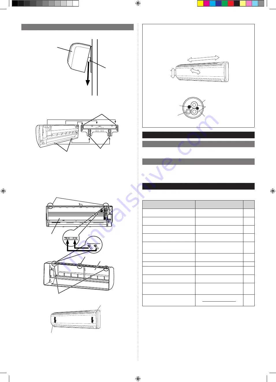
8.2.  Installing front cover

Fix the indoor unit

(1) Please remove the spacer.

Indoor Unit

Remove

Spacer

(2) Hook the 

fi

 ttings of the indoor unit to the 2 bottom hooks while lowering the unit and 

pushing it against the wall.

Bottom hook

Indoor unit

Top hooks

Front panel installation. 

(1)  First, 

fi

 t the lower part of the front panel, and insert top and bottom hooks. (Top center 

and both sides)

(2) Attach the 6 screws.
(3) Attach the intake grille.

Intake grill installation. 

(1) The 

fi

 xing axle of the intake grille is installed on the front panel.

(2) Lay down the intake grille.

Top holes (2 sides)

Top hooks (2 sides)

Top hole (center)

Top hooks (2 sides)

Indoor unit

Top hook (center)

(3) Close the intake grille. 

Intake grille

Panel

Check that:

•  The top and bottom hooks are hooked 

fi

 rmly and the indoor unit does not move to 

the front and rear or left and right.

•  The indoor unit is accurately positioned horizontally and vertically.
•  When connected from the left rear, the drain hose is at the bottom left of the wall 

pipe.

(View from indoor)

Connection cable 
(Power supply cable)

Wall pipe

Connection pipe

Connection cable (Transmission 
and Remote controller cable)

Drain hose

9. TEST 

RUN

9.1.  Test run using Outdoor unit (PCB)

Refer to the Installation Manual for the outdoor unit if the PCB for the outdoor unit is to be 
used for the test run.

9.2.  Test run using remote controller

• Refer to the Installation Manual for the remote controller to perform the test run using the 

remote controller.

• When the air conditioner is being test run, the OPERATION and TIMER indicator lamp 

flash slowly at the same time.

10. CHECK LIST

Pay special attention to the check items below when installing the indoor unit(s). After 
installation is complete, be sure to check the following check items again.

Check items

If not performed correctly

Check 

box

Has the indoor unit been installed 
correctly?

Vibration, noise, indoor unit may 
drop

Has there been a check for gas leaks 
(refrigerant pipes)?

No cooling, No heating

Has heat insulation work been com-
pleted?

Water leakage

Does water drain easily from the indoor 
units?

Water leakage

Is the voltage of the power source the 
same as that indicated on the label on 
the indoor unit?

No operation, heat or burn damage

Are the wires and pipes all connected 
completely?

No operation, heat or burn damage

Is the indoor unit earthed (grounded)?

Short circuit

Is the connection cable the specified 
thickness?

No operation, heat or burn damage

Are the inlets and outlets free of any 
obstacles?

No cooling, No heating

Does start and stop air conditioner 
operation by remote control unit or 
external device?

No operation

After installation is completed, has the 
proper operation and handling been 
explained to the user?

9373370444_IM.indb   15

9373370444_IM.indb   15

29/11/2017   AM 11:48:44

29/11/2017   AM 11:48:44

Содержание Airstage ASUB18TLAV1

Страница 1: ...Français Español MANUEL D INSTALLATION MANUAL DE INSTALACIÓN UNITÉ INTÉRIEURE Type montage mural UNIDAD INTERIOR Tipo montado en pared Pour le personnel agréé uniquement Únicamente para personal de servicio autorizado PART No 9373370444 9373370444_IM indb 1 9373370444_IM indb 1 29 11 2017 AM 11 48 42 29 11 2017 AM 11 48 42 ...

Страница 2: ...aker panel before opening the unit to check or repair electrical parts and wiring Keep your fingers and clothing away from any moving parts Clean up the site after you finish remembering to check that no metal scraps or bits of wiring have been left inside the unit being serviced After installation explain correct operation to the customer using the operating manual DANGER Never touch electrical c...

Страница 3: ...ump adapter A conventional vacuum pump can be used by installing a vacuum pump adapter Be sure that the pump oil does not back flow into the system Use one capable for vacuum suction of 5 Torr 755 mm Hg 100 7 kPa Gas leakage detector Special gas leakage detector for HFC refrigerant R410A 2 3 Accessories WARNING For installation purposes be sure to use the parts supplied by the manufacturer or othe...

Страница 4: ... install the unit where it will be exposed to direct sunlight 3 2 Installation dimension For the drain hose exten sion use a drain hose with a 5 8 in 16 mm inside diameter 71 in 1800 mm or more 60 in 1500 mm or more Right side 8 in 200 mm or more 3 in 60 mm or more Left side 2 in 50 mm or more Wall hook bracket 3 3 Installing the unit WARNING Install the air conditioner in a location which can wit...

Страница 5: ...f copper pipes used with R410A are as shown in the table Never use copper pipes thinner than those indicated in the table even if they are avail able on the market Wall hook bracket Tapping screw big 3 3 2 Cutting the hole in the wall for the connecting piping WARNING If the wall pipe is not used the cable may touch metal and cause electric leakage 1 Cut a 3 1 8 in 80 mm diameter hole in the wall ...

Страница 6: ...A flare tools to achieve the specified flaring Use a thickness gauge to measure the dimension A It is recommended that a R410A flaring tool is used Width across flats Pipe outside diameter in mm Width across flats of Flare nut in mm 1 4 6 35 11 16 17 3 8 9 52 7 8 22 1 2 12 70 1 26 5 8 15 88 1 1 8 29 3 4 19 05 1 7 16 36 4 3 2 Bending pipes The pipes are shaped by your hands or pipe bender Be carefu...

Страница 7: ...nd positively Connect the connection cable firmly to the terminal board Imperfect installation may cause a fire If the supply cable is damaged it must be replaced by the manufacturer its service agent or similarly qualified persons in order to avoid a hazard CAUTION Earth Ground the unit Do not connect the earth ground cable to a gas pipe water pipe lightning rod or a telephone earth ground cable ...

Страница 8: ...WORKS compatible cable Remote con troller cable 2 wire type 22 AWG to 16 AWG 0 33 to 1 25 mm Sheathed PVC cable Non polar 2 core twisted pair 18AWG Thermostat cable 2 core Use sheathed non twisted pair cable Remote con troller cable 3 wire type 22 AWG 0 33 mm Sheathed PVC cable Polar 3 core 6 2 Wiring method Example 2 2 2 Outdoor unit or RB unit 1 Breaker 1 Ground Fault Equipment Breaker GFEB Brea...

Страница 9: ...loose 3 Use the specified cables connect them securely and fasten them so that there is no stress placed on the terminals 4 Use an appropriate screwdriver to tighten the terminal screws Do not use a screwdriver that is too small otherwise the screw heads may be dam aged and prevent the screws from being properly tightened 5 Do not tighten the terminal screws too much otherwise the screws may break...

Страница 10: ...al parts 6 6 1 External input Indoor unit can be Operation Stop Emergency stop or Forced stop by using indoor unit PCB CNA01 or CNA02 Operation Stop mode Emergency stop mode or Forced stop mode can be selected with function setting of indoor unit Indoor unit can be Forced thermostat off by using indoor unit PCB CNA03 or CNA04 A twisted pair cable 22 AWG should be used Maximum length of cable is 49...

Страница 11: ... Connected unit c Select very low current use contacts usable at DC 12 V DC 1 mA or less d The wiring is different from Apply voltage terminals Be sufficiently careful when wiring When connected to Dry contact terminals of multiple indoor units with a connected unit insulate each indoor unit with relay etc as shown on below example K1 CNA02 CNA02 CNA02 K2 K3 K4 K5 K6 Power supply for relay Indoor ...

Страница 12: ...ing when turning ON output to the connected external heater can be set by changing Dip switch on PC board Dip switch SET2 SW3 Fan setting when ON is output to the external heater Explanation OFF Factory setting OFF For the fan setting details see the Design Technical Manual ON ON 7 FIELD SETTING There are 3 methods for address setting by FIELD SETTING as follows Please set by either of the methods...

Страница 13: ...lt in failure 3 Remote controller address i 3 wire type Rotary switch RC AD SW Factory setting 0 When connecting multiple indoor units to 1 standard wired remote controller set the address at RC AD SW in sequence from 0 Setting Setting range Type of switch Remote controller ad dress 0 to 15 Setting example 0 RC AD Example If 4 indoor units are connected Remote controller Indoor unit Indoor unit In...

Страница 14: ...t Stop Allow an external controller to start or stop the system or to perform an emergency stop If an emergency stop is performed from an external controller all refrigerant sys tems will be disabled If forced stop is set indoor unit stops by the input to the external input terminals and Start Stop by a remote controller is restricted 01 Emergency stop 02 Forced Stop Error report target 47 00 All ...

Страница 15: ... Green TIMER indicator lamp Orange FILTER indicator lamp Red 10 sec 1 cycle 12 sec 8 sec ON OFF 0 5s 0 5s 0 5s 0 5s 0 5s 0 5s 0 5s 0 5s 0 5s 0 5s 0 5s 0 5s ON OFF ON OFF ON Refrigerant address example Example ADDRESS 30 OPERATION indicator lamp Green TIMER indicator lamp Orange FILTER indicator lamp Red 9 sec 1 cycle 12 sec ON OFF 1 0s 1 0s 1 0s 1 0s 1 0s 1 0s 1 0s 0 5s 0 5s 0 5s 0 5s 0 5s 0 5s ON...

Страница 16: ...e used for the test run 9 2 Test run using remote controller Refer to the Installation Manual for the remote controller to perform the test run using the remote controller When the air conditioner is being test run the OPERATION and TIMER indicator lamp flash slowly at the same time 10 CHECK LIST Pay special attention to the check items below when installing the indoor unit s After installation is...

Страница 17: ...1 Indoor unit room temp thermistor error 4 2 Indoor unit heat ex temp thermistor error 5 1 Indoor unit fan motor 1 error 5 2 Indoor unit coil expansion valve error 5 3 Indoor unit water drain abnormal 9 15 Outdoor unit miscellaneous error 10 8 Poor refrigerant circula tion 13 1 RB unit error Display mode 0 5s ON 0 5s OFF 0 1s ON 0 1s OFF Number of flashing Wired remote controller display UTY RNKU ...

Отзывы: