


En-6
CAUTION
• There should be no gaps between the insulation and the unit.
• After checking for gas leaks (refer to the Installation Manual of the outdoor unit),
perform this section.
• Install heat insulation around both the large (gas) and small (liquid) pipes. Failure to
do so may cause water leaks.
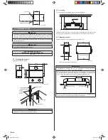
5. INSTALLING DRAIN PIPES
5.1. Installing drain pipes (Ceiling concealed type)
CAUTION
• Install the drain pipe in accordance with the instructions in this Installation Manual
and keep the area warm enough to prevent condensation. Problems with the piping
may lead to water leaks.
Install the drain pipes according to the measurements given in the following
fi
gure.
Flange positions for connecting the drain pipes.
139
123
108
41
208
356
371
Main drain pipe
ø25.4 (O.D.)
Safety drain pipe
ø25.4 (O.D.)
Unit : mm
CAUTION
• This UNIT has drain ports in two locations. Follow the procedure in the figure to
connect drain pipes to each of them.
• Be sure to properly insulate the drain pipes.
Use general hard polyvinyl chloride pipe (VP25) and connect it with adhesive (polyvinyl
chloride) so that there is no leakage.
Do not perform air bleeding.
(1) Main drain pipe
Provide one trap on the main drain pipe near the indoor unit.
H
1
H
2
Trap
Unit
H
1
= 100 mm (approx.)
H
2
= 50-100 mm
Drain pipe (main)
(2) Safety drain
There is no need to provide a trap for the safety drain pipe. If the safety drain pipe is
connected to the main drain pipe, make the connection below the trap on the main drain
pipe.
Drain pipe (main)
Drain pipe (safety)
Unit
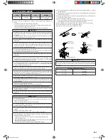
•
Once installation is complete, check the
fl
ow of the drain water.
(1) Detach the caps and plugs from the pipes.
(2) Centering the pipe against port on the indoor unit, turn the
fl
are nut with your hand.
Flare nut
Connection pipe
(small)
Connection pipe
(large)
Flare nut
(3) When the
fl
are nut is tightened properly by your hand, hold the body side coupling
with a separate spanner, then tighten with a torque wrench. (See the table below for
the
fl
are nut tightening torques.)
CAUTION
• Hold the torque wrench at its grip, keeping it at a right angle with the pipe, in order to
tighten the
fl
are nut correctly.
• Tighten the
fl
are nuts with a torque wrench using the speci
fi
ed tightening method.
Otherwise, the
fl
are nuts could break after a prolonged period, causing refrigerant to
leak and generate a hazardous gas if the refrigerant comes into contact with a
fl
ame.
• Connect the piping so that the control box cover can easily be removed for servicing
when necessary.
• In order to prevent water from leaking into the control box, make sure that the piping
is well insulated.
Tighten with 2 wrenches.
Holding wrench
Flare nut
Connection pipe
Torque wrench
Indoor unit pipe
(Body side)
Flare nut [mm (in.)]
Tightening torque [N·m (kgf·cm)]
6.35 (1/4) dia.
16 to 18 (160 to 180)
9.52 (3/8) dia.
32 to 42 (320 to 420)
12.70 (1/2) dia.
49 to 61 (490 to 610)
15.88 (5/8) dia.
63 to 75 (630 to 750)
19.05 (3/4) dia.
90 to 110 (900 to 1,100)
4.4. Installing heat insulation
After checking for gas leaks, insulate by wrapping insulation around the two parts (Gas
and Liquid) of the indoor unit coupling, using the coupler heat insulation.
After installing the coupler heat insulation, wrap both ends with vinyl tape so that there is
no gap.
Secure both ends of the heat insulation material using nylon fasteners.
Coupler heat insulation (Small)
Coupler heat insulation (Large)
Indoor unit side
9379123037-02.indb 6
9379123037-02.indb 6
7/4/12 3:47 PM
7/4/12 3:47 PM


