


En-4
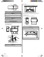
450
500
500
Control box
Maintenannce hole
Unit : mm
3.3. Installation the unit
WARNING
• Install the air conditioner in a location which can withstand a load do at least 5
times the weight of the main unit and which will not amplify sound or vibration. If the
installation location is not strong enough, the indoor unit may fall and cause injuries.
• If the job is done with the panel frame only, there is a risk that the unit will come
loose. Please take care.
CAUTION
• For installation, refer to the technical data.
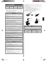
RECOMMENDED RANGE OF
EXTERNAL STATIC PRESSURE [Pa]
100 - 250
3.3.1. Installing the hangers
Hanging bolt installation diagram
460
155
585
500
85
Unit : mm
AIR
AIR
AIR
1,080
1,000
1,050
Hanging bolt M10
(Obtained locally)
Washer
(Obtained
locally)
Special nut A
Hanger
Special nut B
CAUTION
• Fasten the unit securely with special nuts A and B.
3.3.2. Leveling
Use the procedure in the following
fi
gure to adjust the levelness.
B
A
Level meter
The side A of the unit with the drain port should be slightly lower than the opposite side
B of the unit. The height difference between sides A and B should be from 0 to 20mm.
3.3.3. Mounting the duct
Follow the procedure in the following
fi
gure to install the ducts.
865
850
26
295
14
325
14
27
Intake port
fl
ange
Outlet port
fl
ange
Unit : mm
Spacing between
fl
ange and drain pan.
CAUTION
• If an intake duct is installed, take care not to damage the temperature sensor (the
temperature sensor is attached to the intake port
fl
ange).
• Be sure to install the air inlet grille and the air outlet grille for air circulation. The
correct temperature cannot be detected. Grills must be installed so that man cannot
touch unit fan, and cannot be removed by only hand operation with tool.
Air Inlet Grille
Air Outlet Grille
(Room)
Unit
• Be sure to install the air
fi
lter in the air inlet. If the air
fi
lter is not installed, the heat
exchanger may be clogged and its performance may decrease.
9379123037-02.indb 4
9379123037-02.indb 4
7/4/12 3:47 PM
7/4/12 3:47 PM


