FT500 SFI / FT500LITE SFI
52
Sensors and Calibration
Gear detection 4/5
Rising edge
Falling edge
Signal edge
Gear detection 6/7
External button
2-Step
Gear reset
Activated at 12V
Activated at 0V
Button mode
The fifth mode enables an internal counter that is increased by each
pulse sent out by the Gear shift output (Drag Race Features menu).
This mode cannot detect downshifts and requires the 2-step to be
used to reset the counter; therefore it is best suited for drag race cars.
Gear detection 2/5
Analog Sensor
RPM drop
By wheel speed
or driveshaft
Gear shift
based output
By input signal
Detection type
15.11 Nitrous bottle pressure
This menu gathers the settings to read nitrous bottle pressure. This way
is possible do compensate fuel according to the bottle pressure. To read
the bottle pressure you must use a PS1500 sensor or a similar one.
15.12 Clutch position
In this menu are the settings to read the clutch position. A potentiometer
must be used, similar to a TPS. After the wiring done, the calibration
is required.
Clutch position 1/2
White 7: Air temperature
Input selection
White 9: Avaliable
White 8: Avaliable
White 10: MAP signal
White 11: TPS
Reading
Position at 0%
Position at 100%
4.99V
Calibrate
4.99V
4.99V
Calibrate
Clutch position 2/2
Gear detection 6/7
External button
2-Step
Gear reset
Activated at 12V
Activated at 0V
Button mode
15.13 Clutch pressure
This function allows to measure the pressure of the liquid on hydraulic
assisted clutches. To read the pressure, use a PS1500 sensor or a
similar one.
Clutch pressure 1/3
White 6: Fuel pressure
Input selection
White 8: Avaliable
White 7: Air temperature
White 9: clutch
White 10: MAP signal
Pressure sensor type
1450 PSI / PS100 (1,0 5,0V)
a
1500
(0,5 a 4,5V)
PSI
Clutch pressure 2/3
Custom
Input value
Output value
Sensor offset
+0,3
PSI
1350,0
PSI
Reading
Clutch pressure 3/3
15.14 Ride Height
This function allows to read the front end height from the ground. The
wheelie control is based on this input and you can find more on this
at Chapter 20.9. Normally, a laser height sensor is used.
Ride height 1/2
None
Input selection
White 2: Avaliable
White 1: O2 sensor #1
White 3: 2-step
White 4: Oil pressure
Input value
Output value
Ride height 2/2
Sensor offset
+0,3
3,5
in
Reading
in
Pitch rate 1/2
None
Input selection
White 2: Pitch rate
White 1: O2 Sensor
White 3: 2-step
white 4: Oil pressure
Input value
Sensor value
Pitch rate 2/2
Sensor offset
+0,6
0,0
°/S
Reading
°/S
15.15 Pitch Rate
This function reads the rate at the front end pitches and is given by
degrees per second.
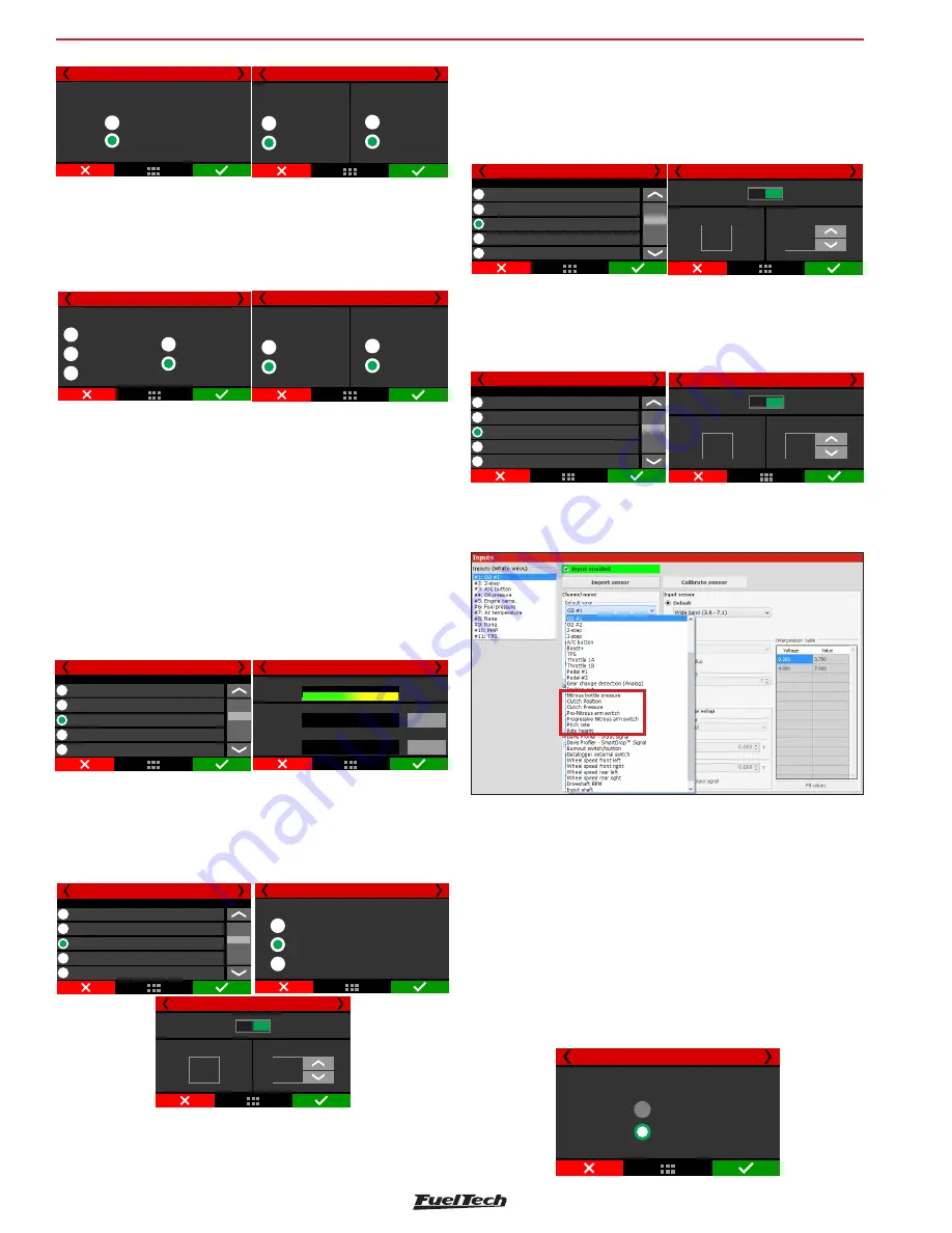
Through FTManager, all the sensors above can be configured in the
“Sensors and Calibration” menu, then “Inputs”.
15.16 CAN communication
In this menu is possible to configure all the equipment connected to
the CAN network. There are 2 different CAN protocols. Below is the
compatibility of each protocol:
-
FTCAN 1.0: GearController (until V2.17), BoostController,
KnockMeter, Racepak IQ3 and AiM Dashes;
-
FTCAN 2.0: GearController (after V2.20) EGT-8 CAN; WB-O2
Nano and WB-O2 Slim;
CAN network supports up to 32 sensors of each product.
CAN communication 1/2
CAN mode
FTCAN 1.0
FTCAN 2.0


