background image

4

LOCATION OF YOUR WASHER

DO NOT INSTALL YOUR WASHER:

1.

In an area exposed to dripping water or outside weather
conditions. The ambient temperature should never be below
60 degrees F (15.6 degrees C) for proper washer operation.

2.

In an area where it will come in contact with curtains or drapes.

3.

In an area (garage or garage-type building) where gasoline of
other flammables are kept or stored (including automobiles).

4.

On carpet. Floor 

MUST

 be solid with a maximum slope of 1/2

in. per foot (1.27 cm per 30.5 cm). To ensure vibration or
movement does not occur, reinforcement of the floor may be
necessary.

IMPORTANT
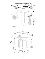
MINIMUM INSTALLATION CLEARANCES

When installed in alcove: Sides, Rear, Top = 0 in
(0 cm).
When installed in closet: Sides, Rear, Top = 0 in
(0 cm), Front = 1 in (2.54 cm).
Closet door ventilation openings required:  2 louvers each 60 in

2

(387 cm

2

) - 3 in (7.6 cm) from top and bottom of door.

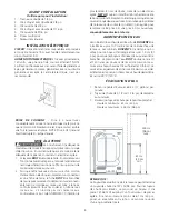
UNPACKING

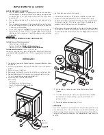
1. Cut the shipping carton along the dotted line along the base of


the unit.

2. While in the carton carefully lay the washer on its back side.
3. Remove the styrofoam base.
4. Carefully return the  washer to an upright position and remove


the  carton.

5. Carefully move the washer to within 4 feet (122cm) of the final


 location.

6. Remove the following from the back side of the washer:
    3 bolts,
    3 yellow plastic spacers,
    2 or 3 metal "P" clamps.

 10.  Remove and discard the yellow ribbon and label from the
         front of the washer.
 11.  From the rear of the washer, carefully pull out the power
        supply cord through the hole in the backsheet.
 12.  Replace the service panel and screws.

  NOTE:

  If the washer is tobe transported at a later date,the shipping

         support hardware must be reinstalledto prevent shipping
           damage.

7. Remove the service panel from the front of the washer.
8. Remove the 4 nuts and 6 large washers that attach the 2 yellow

shipping braces to the drum and the base. Lift up on the drum
and remove the braces (a yellow ribbon surrounds the

   items to be removed). These braces must be removed to allow the
   power supply cord to be released from the shipping ring.
9. Remove the large styrofoam block located under the drum. Lift up

on the drum, tilt the base of the foam block inwards toward the
rear of the washer until free, then pull it out.

BOLT

SPACER

"P" CLAMP

Содержание CTF140ES0

Страница 1: ...uedelalaveusedoitrespecterlescodesetordonnanceslocauxainsiquel éditionlaplusrécentedu Code ANSI NFPA 70 ou au Canada le Code canadien d électricité ACNOR C22 1 partie1 Pour votre sécurité suivre les directives données dans le présent guide afin de minimiser les risques d incendie d explosion de dommages matériels de blessures et de mort Ne pas entreposer ni utiliser d essence ou d autres vapeurs o...

Страница 2: ...eriod before using the washer turn on all hot water faucets and let the water flow from each for several minutes This will release any accumulated hydrogen gas Hydrogen gas is flammable do not smoke or use an open flame during this time Failure to comply with these warnings could result in fire explosion serious bodily injury and or damage to the rubber or plastic parts of the washer Protect Child...

Страница 3: ...al shock Check with a licensed electrician if you are in doubt as to whether the appliance is properly grounded 1 The washer MUST be grounded In the event of malfunction or breakdown grounding will reduce the risk of electrical shock by a path of least resistance for electrical current 2 Since your washer is equipped with a power supply cord having an equipment grounding conductor and a grounding ...

Страница 4: ...its back side 3 Remove the styrofoam base 4 Carefully return the washer to an upright position and remove the carton 5 Carefully move the washer to within 4 feet 122cm of the final location 6 Remove the following from the back side of the washer 3 bolts 3 yellow plastic spacers 2 or 3 metal P clamps 10 Remove and discard the yellow ribbon and label from the front of the washer 11 From the rear of ...

Страница 5: ...with your laundering tasks INSTALLATION 1 Run some water from the hot and cold faucets to flushthe water lines and remove particles that might clog up the water valve screens 2 Remove the inlet hoses and rubber washers from the plastic bag and install the rubber washers in each end of the inlet hoses 3 90 elbow end Carefully connect the inlet hose marked HOT to theoutside H outlet of the water val...

Страница 6: ... to establish the warranty period should service be required If service is performed it is in your best interest to obtain and keep all receipts Service under this warranty must be obtained by contacting Electrolux at the addresses or phone numbers below Your appliance is covered by a one year limited warranty For one year from your original date of purchase Electrolux will pay all costs except as...

Страница 7: ...s graves ou la mort Ne pas utiliser plus d un seul produit à lessive par brassée à moins d indications contraires sur l emballage Ne pas mélanger d eau de javel avec de l ammoniaque ou des produits acides comme le vinaigre Pour prévenir les blessures graves et ne pas endommager la laveuse Les réparations et l entretien doivent être effectués uniquement par un agent de service autorisé à moins d in...

Страница 8: ... 24 po min 244 cm 96 po max ARRIÈRE PRISE DE COURANT Prise à 3 ouvertures convenablement mise à la terre et située de façon à ce que le cordon d alimentation électrique soit accessible une fois la laveuse en place NOTE Prise à GFI Ground FaultInterrupter n estpasrequise MISE À LA TERRE Le branchement inadéquat du conducteurdemiseàlaterrepourraitprésenterunrisque d électrocution En cas de doute qua...

Страница 9: ...9 DIMENSIONS DE L EMPLACEMENT 43 2 17 Côté Cordon d alimentation Pieds de nivellement 8 43 8 v 20 4 11 2 Arrière Robinets d arrivée d eau ...

Страница 10: ...délicatement la laveuse à la verticale puis retirer le carton 5 Déplacer délicatement la laveuse jusqu à ce qu elle soit à environ 122 cm 4 pieds de son emplacement définitif 6 Retirer les pièces suivantes de l arrière de la laveuse 3 boulons 3 entretoises en plastique jaunes 2 ou 3 attaches métalliques en forme de P 10 Retirer et jeter le ruban jaune et l étiquette du devant de la laveuse 11 A l ...

Страница 11: ...orgerlefiltredes robinets 2 Enlevez du sac en plastique les tuyaux d arrivée et les rondelles caoutchouc et installez les rondelles à chaque extrémité 3 Quantre vingt dixdegrédescoudes Branchez soigneusement le tuyau d arrivée marqué HOT CHAUDE à la sortie inférieure de la soupape d eau Serrez à la main puis serrez encore de 2 3detouràl aidedepinces Branchezsoigneusementl autretuyau COLD FROIDE d ...

Страница 12: ...on électrique inadéquate ou les cas de force majeure 17 Les coûts de main d œuvre suivant quatre vingt dix 90 jours de la date originale d achat engagés pour la réparation ou le remplacement de produit tel que stipulé aux présentes pour les appareils opérés par un concessionnaire ou un vendeur dans une remorque ou un autre véhicule motorisé ou dans divers emplacements AVIS DE NON RESPONSABILITÉ SU...

Отзывы: