110
PB
R-410A SEALED SYSTEM REPAIR
Compressor replacement
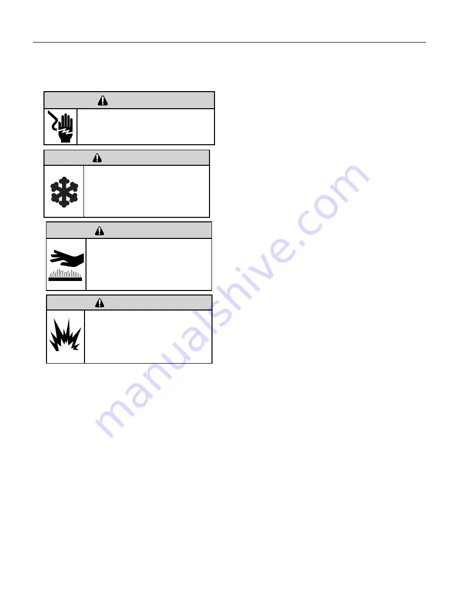
WARNING
ELECTRIC SHOCK HAZARD
Disconnect power to the unit before
servicing. Failure to follow this warning
could result in serious injury or death.
BURN HAZARD
Proper safety procedures must be followed,
and proper protective clothing must be worn
when working with a torch.
Failure to follow these procedures could
result in moderate or serious injury.
WARNING
FREEZE HAZARD
Proper safety procedures must be followed,
and proper protective clothing must be worn
when working with liquid refrigerant.
Failure to follow these procedures could
result in minor to moderate injury.
CAUTION
WARNING
EXPLOSION HAZARD
The use of nitrogen requires a pressure
regulator. Follow all safety procedures and
wear protective safety clothing etc.
Failure to follow proper safety procedures
could result in serious injury or death.
1. Be certain to perform all necessary electrical and refrigeration tests
to be sure the compressor is actually defective before replacing.
2. Recover all refrigerant from the system though the process tubes.
PROPER HANDLING OF RECOVERED REFRIGERANT ACCORDING TO
EPA REGULATIONS IS REQUIRED. Do not use gauge manifold for
this purpose if there has been a burnout. You will contaminate your
manifold and hoses. Use a Schrader valve adapter and copper tubing
for burnout failures.
3.After all refrigerant has been recovered, disconnect suction and
discharge lines from the compressor and remove compressor. Be
certain to have both suction and discharge process tubes open to
atmosphere.
4.Carefully pour a small amount of oil from the suction stub of the
defective compressor into a clean container.
5.Using an acid test kit (one shot or conventional kit), test the oil for
acid content according to the instructions with the kit.
6.If any evidence of a burnout is found, no matter how slight, the
system will need to be cleaned up following proper procedures.
7.Install the replacement compressor.
8. Pressurize with a combination of R‑410A and nitrogen and leak
test all connections. If a leak cannot be found, pressurize with a
combination of Nitrogen and a trace charge of R‑410A and sweep with
with an electronic or Halide leak detector. Recover refrigerant and
repair any leaks found.
8a. If leak detector is unavailable remove all refrigerant from system
and pressurize with nitrogen to 550 psi. Check that system holds
pressure.
Repeat Step 8 to insure no more leaks are present
9. Evacuate the system with a good vacuum pump capable of a final
vacuum of 200 microns or less. The system should be evacuated
through both liquid line and suction line gauge ports. While the unit
is being evacuated, seal all openings on the defective compressor.
Compressor manufacturers will void warranties on units received not
properly sealed. Do not distort the manufacturers tube connections.
10. Recharge the system with the correct amount of refrigerant. The
proper refrigerant charge will be found on the unit rating plate. The
use of an accurate measuring device, such as a charging cylinder,
electronic scales or similar device is necessary.
Содержание VRP12K
Страница 30: ...30 OPERATION FreshAire Control To engage the FreshAire system flip the switch into the ON position ...
Страница 46: ...46 OPERATION Component Identification Indoor Coil 36k ...
Страница 47: ...47 OPERATION Component Identification Indoor Blower BLDC Counter Clockwise Impeller 600 1300 RPM ...
Страница 48: ...48 OPERATION Component Identification Outdoor Coil Monitored by 1 thermistor ...
Страница 49: ...49 OPERATION Component Identification Outdoor Fan BLDC Variable Speed 600 1000 RPM ...
Страница 53: ...53 OPERATION Component Identification 4 Way Reversing Valve 208 230v Reversing valve assembly ...
Страница 177: ...177 UPDATING VRP FIRMWARE Or ...
Страница 184: ...184 UPDATING VRP FIRMWARE Open zip file Copy to SD Card Insert into SD Card Slot ...
Страница 193: ...193 UPDATING VRP FIRMWARE Retrieving VRP Data Remove SD Card from FMC and Locate DF Folder ...
Страница 194: ...194 UPDATING VRP FIRMWARE Retrieving VRP Data Right Click Data txt Send to Compressed zipped folder ...
Страница 196: ...196 WIRINGDIAGRAMS 12 24K BTU 208 230V 7 5 10 0 KW Figure 801 Wiring Diagram ...
Страница 197: ...197 WIRING DIAGRAMS 12 24K BTU 208 230V 2 5 3 4 5 0 KW Figure 802 Wiring Diagram ...
Страница 198: ...198 WIRING DIAGRAMS 12 24K BTU 265V 2 5 3 4 5 0 kW Figure 803 Wiring Diagram ...
Страница 199: ...199 WIRING DIAGRAMS 12 24K BTU 265V 7 5 10 kW Figure 804 Wiring Diagram ...
Страница 200: ...200 WIRING DIAGRAMS 36K BTU 208 230V Figure 805 Wiring Diagram ...
Страница 214: ...214 PARTS CATALOG 36k Control Box Diagram Figure 906 12 12 11 13 10 8 4 3 2 16 5 6 7 1 9 10 9 10 11 11 14 15 ...


