6. Installation
6. Instalacja
6. Installatie
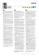
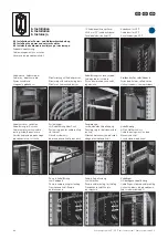
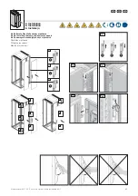
6.1 Installing the customer hardware
Before populating the VX IT with equipment,
it must first be secured to the floor. Please
use base mounting bracket 5301.350 for this
purpose.
The loads of the installed equipment and the
maximum admissible payload of the VX IT
must be observed. Also, when using installa-
tion accessories, please observe the specified
load capacity.
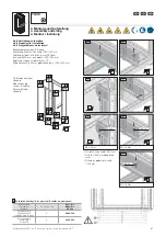
Check the 482.6 mm (19˝) distances between
levels and make corrections where necessary
(see page 95 – 100).
The installation of equipment must conform
with the relevant provisions on the installed
equipment. Before configuring the VX IT,
please determine the positions of all compo-
nents. The factors of the relevant components,
such as weight, accessibility and the require-
ments placed on the power supply, tempera-
ture and air circulation, affect the sequence
and location of component positioning in the
rack.
◾ Always place the heaviest components at
the bottom of the VX IT. This will help to
increase stability.
◾ Always ensure the correct fastening and
safe positioning of all components and rack
assemblies. Please also observe the torque
information (M
A
) for the screw connections.
◾ Preinstalled VX IT on castors may only be
moved if the centre of gravity of the instal-
lation is below the 13th height unit from the
bottom.
◾ At least two persons are required to assem-
ble and dismantle assemblies or compo-
nents weighing more than 25 kg.
◾ Only use safe electrical devices; this unit is
not designed as a Class 1 enclosure.
◾ Only use approved, safe terminal equipment
intended for mounting on 482.6 mm (19˝)
mounting angles or for rack installation using
other equipment (slide rails, component
shelves).
◾ Additional installation weights on doors
or side panels are only admissible if using
sheet steel doors and side panel from the
VX25 industry range. The maximum installa-
tion weight per panel is 90 kg.
◾
Caution when using telescopic slides:
The VX IT must be secured to the floor or
bayed with other VX IT or, alternatively, the
stabiliser (5301.325) must be used before
extending equipment on telescopic slides.
Only one device at a time may be in the set
forward position. If for some reason more
than one device is extended at the same
time, the stability of the VX IT may be at risk.
Failure to follow these instructions may lead to
serious injury, damage to property or, in the
worst case, even death.
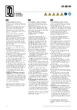
6.1 Instalacja sprzętu klienta
Przed zainstalowaniem sprzętu, VX IT musi
zostać przymocowana do podłoża. Do tego
celu należy użyć kątownik mocujący do pod-
łogi 5301.350.
Przestrzegać ciężarów komponentów
zabudowy i maksymalnego dopuszczalnego
ciężaru użytkowego VX IT. Poza tym należy
uwzględnić nośność wykorzystanych akceso-
riów do rozbudowy.
Sprawdzić odległości płaszczyzn 19˝ i
w razie potrzeby dokonać korekty
(p. str. 95– 100).
Instalacja urządzeń musi być zgodna z odpo-
wiednimi przepisami dotyczącymi instalowania
urządzeń elektrycznych oraz urządzeń techniki
przetwarzania danych.
Przed wyposażeniem VX IT należy określić
rozmieszczenie wszystkich komponentów.
Cechy poszczególnych komponentów, jak
ciężar, dostępność oraz wymagania odno-
śnie zasilania elektrycznego, temperatury i
cyrkulacji powietrza, mają wpływ na kolejność
i miejsce, w którym zostaną zainstalowane.
◾ Najcięższe komponenty zawsze umieszczać
na dole VX IT. W ten sposób zwiększa się
stateczność.
◾ Zawsze należy zwracać uwagę na prawi-
dłowe zamocowanie i bezpieczne położenie
wszystkich komponentów i podzespołów.
Należy tutaj również przestrzegać podanych
wartości momentów dokręcania (M
A
) połą-
czeń śrubowych.
◾ Preinstalowane VX IT można przemieszczać
na rolkach tylko wtedy, gdy punkt ciężkości
instalacji znajduje się poniżej 13 jednostki
wysokości od dołu.
◾ Do montażu i demontażu komponentów lub
podzespołów ważących więcej niż 25 kg
potrzeba co najmniej dwóch osób.
◾ Stosować wyłącznie bezpieczne urządzenia
elektryczne – szafa nie jest obudową
klasy 1.
◾ Stosować tylko dopuszczone, bezpieczne
w zastosowaniu urządzenia końcowe, które
są przeznaczone do montażu na szynach
profilowych 19˝ lub za pomocą innych
elementów pomocniczych (szyny ślizgowe,
półki urządzeniowe itp.) do instalacji w
szafach typu rack.
◾ Dodatkowe obciążenia drzwi lub ścian
bocznych są dozwolone tylko pod warun-
kiem zastosowania drzwi z blachy stalowej i
ścian bocznych z oferty przemysłowej
VX25. Maksymalny ciężar zabudowy na
część płaską wynosi 90 kg.
◾
Uwaga w przypadku stosowania szyn
teleskopowych:
Przed wysuwaniem
urządzeń na szynach teleskopowych VX IT
musi zostać przymocowana do podłoża lub
połączona w szereg z inną VX IT, albo należy
zastosować zabezpieczenie przed przewró-
ceniem (5301.325). W wysuniętej pozycji
może znajdować się tylko jedno urządzenie
na raz. Jeżeli z jakichkolwiek powodów
zostanie wysuniętych więcej niż jedno urzą-
dzenie, może to zagrozić stabilności VX IT.
Nieprzestrzeganie tych instrukcji może
prowadzić do poważnych obrażeń, szkód
materialnych lub w najgorszym przypadku
również do śmierci.
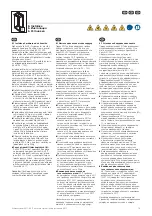
6.1 Installatie van hardware van de klant
Voordat er apparaten in het VX IT-rack worden
gemonteerd, moet het rack aan de vloer
worden verankerd. Gebruik hiervoor a.u.b. de
bodembevestigingsbeugels 5301.350.
Neem het gewicht van de inbouwcomponen-
ten en het max. toelaatbare laadvermogen
van het VX IT-rack in acht. Daarnaast moet bij
het gebruik van opbouwtoebehoren rekening
worden gehouden met de vermelde draagca-
paciteit.
Controleer de 19˝-niveau-afstanden en
corrigeer deze indien nodig
(zie pag. 95 – 100).
De installatie van de apparaten moet voldoen
aan de betreffende bepalingen voor het instal-
leren van elektrische apparaten en apparaten
voor de gegevensverwerkingstechniek.
Voordat u het VX IT-rack monteert, moet u
de locatie van alle componenten vastleggen.
Bepaalde factoren van de betreffende com-
ponenten, zoals gewicht, bereikbaarheid en
eisen op het gebied van voeding, temperatuur
en luchtcirculatie, zijn van invloed op de vol-
gorde waarin en de locatie waar de compo-
nenten in het rack worden geplaatst.
◾ Plaats de zwaarste componenten steeds
onder in het VX IT-rack. Dit vergroot de
stabiliteit.
◾ Zorg altijd dat alle componenten en rack-
-onderdelen correct en veilig zijn bevestigd
en gepositioneerd. Neem hiervoor ook de
aandraaimomenten (M
A
) van de schroef-
verbindingen in acht.
◾ Voorgeïnstalleerde VX IT-racks op wielen
mogen alleen worden verplaatst wanneer
het zwaartepunt van de installatie lager
ligt dan de 13e hoogte-eenheid vanaf de
onderzijde.
◾ Voor componenten die meer dan 25 kg
wegen, zijn bij de montage en demontage
ten minste twee personen nodig.
◾ Gebruik alleen elektrisch betrouwbare
apparaten – niet bestemd voor toepassing
als klasse 1 rack.
◾ Gebruik alleen toegelaten, betrouwbare ein-
dapparaten die geschikt zijn voor montage
aan 19˝-profielen of met behulp van andere
hulpmiddelen (glijrails, legborden, etc.) in
een rack zijn te installeren.
◾ Extra inbouwgewichten in deuren of zijwan-
den zijn alleen toegelaten bij toepassing
van plaatstalen deuren en zijwanden uit het
industriële VX25-productassortiment. De
max. inbouwbelasting per vlak deel bedra-
agt 90 kg.
◾
Aandachtspunt bij het gebruik van tele-
scooprails:
alvorens apparaten op telesco-
oprails naar buiten te trekken, moet het VX
IT-rack aan de vloer worden verankerd, aan
andere VX IT-racks zijn gekoppeld of moet
er een kantelbeveiliging (5301.325) worden
toegepast. Er mag slechts één apparaat
tegelijk naar buiten zijn getrokken. Het om
wat voor reden dan ook naar buiten trekken
van meer dan één apparaat tegelijk brengt
de stabiliteit van het VX IT-rack in gevaar.
Het niet volgen van deze instructies kan
materiële schade, ernstig letsel of zelfs de
dood tot gevolg hebben.
70
Schranksystem VX IT / VX IT enclosure system / Szafy systemowe VX IT


