Descriptions of LEFT and RIGHT are from the point of view of standing
behind the equipment facing the front
6
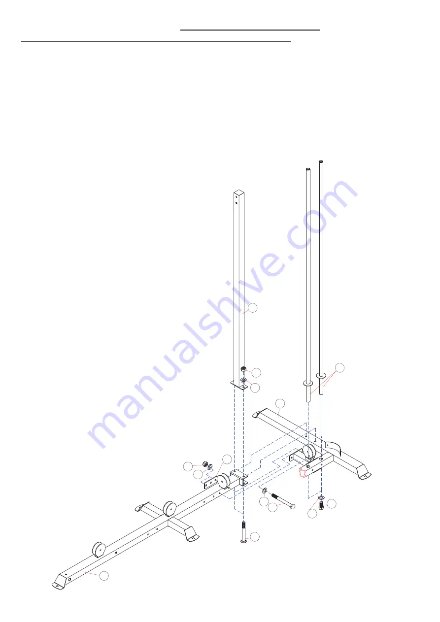
ASSEMBLY DIAGRAM 1
USE A PARTNER TO HELP WITH THIS STEP
REMEMBER: Only hand tighten all nuts and bolts until whole
&&Ͳ
X
ϰ
is assembled
1.
Ensuring correct orientation, slot the bracket on the end of BASE FRAME (13) over the bolt holes in the centre of the
REAR BASE FRAME (1)
2.
Position the REAR VERTICAL FRAME (2) over the same point and attach all three parts together from underneath
using two CARRIAGE BOLT M10X80 (123), two WASHER10 (92) and two AIRCRAFT NUT M10 (97)
3.
Position a BRACKET (124) on the right side of the BASE FRAME (13) level with the rear pulley bracket.
4.
Connect the BRACKET (124), the BASE FRAME (13) and the REAR BASE FRAME (1) together using two HEX BOLT
M10X95 (109), four WASHER10 (92) and two AIRCRAFT NUT M10 (97)
5.
Slot the two GUIDE RODS (5) into the slots on the REAR BASE FRAME (1) and connect from underneath using two HEX
BOLT M10X20 (99) and two WASHER10 (92)
Содержание FF-X4
Страница 25: ...25 HARDWARE 0 h H ROW 4W 0 h H ROW 4W 0 h H ROW 4W PP 0 h H ROW 4W 0 h H ROW 4W 0 h H ROW 4W...
Страница 26: ...26 0 h OOHQ ROW 4W PP 0 h OOHQ ROW 4W 0 h H ROW 4W 0 h H ROW 4W 0 h H ROW 4W 0 h H ROW 4W...
Страница 27: ...27 DVKHU 4W 0 LUFUDIW 1XW 4W PP 0 h 3KLOLSV 6FUHZ 4W 0 LUFUDIW 1XW 4W 0 LUFUDIW 1XW 4W h h DVKHU 4W DVKHU 4W...
Страница 28: ...28 0 h OOHQ ROW 4W 0 h H ROW 4W PP 0 h H ROW 4W 0 h H ROW 4W 0 h H ROW 4W 0 h H ROW 4W 0 h H ROW 4W...
Страница 30: ...30 6KRUW KDLQ 4W RQJ KDLQ 4W PP RRN 4W h0 h OH 4W h h 3XOOH XVKLQJ 4W...


