Descriptions of LEFT and RIGHT are from the point of view of standing
behind the equipment facing the front
17
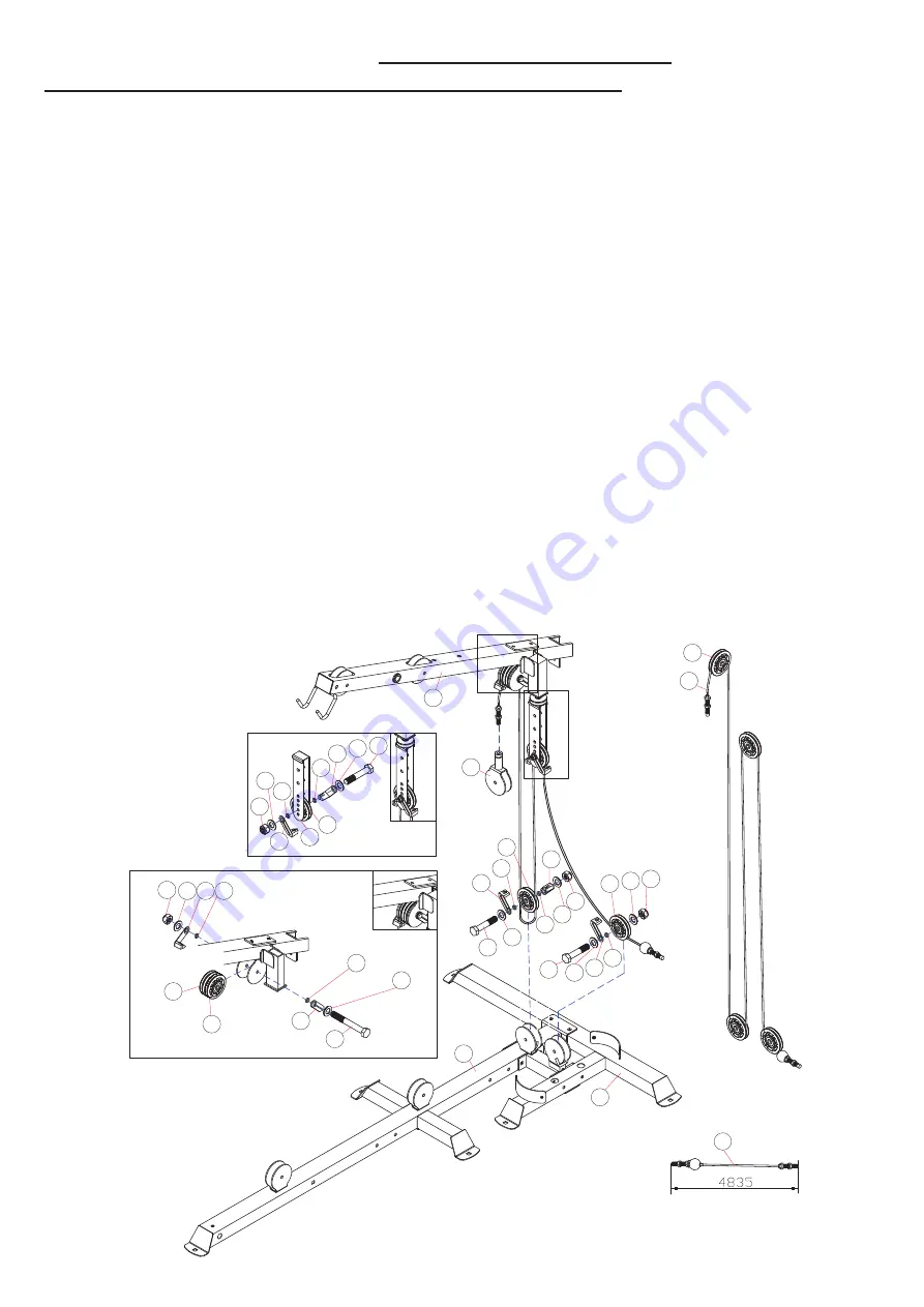
ASSEMBLY DIAGRAM 1
USE A PARTNER TO HELP WITH THIS STEP
REMEMBER: Only hand tighten all nuts and bolts until whole
&&Ͳ
X
ϰ
is
DVVHPEOHG
(HINT: Work your way from the stoppered end of the cable to the other, connecting one pulley at a time and ensuring
everything is positioned correctly before continuing. Ensure the cable retainers are all correctly angled)
1.
Position the stoppered end of CONNECTABLE CABLE (42) in the rear left pulley bracket on the REAR BASE FRAME (1)
2.
Insert a PULLEY (79), ensuring the cable runs under the pulley. Attach using a HEX BOLT M10X50 (102), a WASHER10
(92), a CABLE RETAINER (86), and a CABLE RETAINER BUSHING (85); on the front outer side of the bracket; and a
WASHER10 (92) and an AIRCRAFT NUT M10 (97) on the rear outer side.
3.
Draw the cable upward to the ADJUSTABLE PULLEY BRACKET (17) under the left rear of the UPPER FRAME (4)
DIAGRAM A
. Insert a PULLEY (79) into a lower bolt hole, ensuring the cable runs over the pulley. Attach using a HEX
BOLT M10X55 (103),with a WASHER10 (92), a CABLE RETAINER (86), and a CABLE RETAINER BUSHING (85) on each
outer side of the bracket. Secure with an AIRCRAFT NUT M10 (97)
4.
Draw the cable downward to the pulley bracket at the rear of the BASE FRAME (13)
5.
Insert a PULLEY (79) into the bracket, ensuring the cable runs under the pulley from left to right. Attach using a HEX
BOLT M10X55 (103), with a WASHER10 (92), a CABLE RETAINER (86), and a CABLE RETAINER BUSHING (85) on each
outer side of the bracket. Secure with an AIRCRAFT NUT M10 (97)
6.
Draw the cable upward to the pulley bracket under the rear of the UPPER FRAME (4)
DIAGRAM B
it will still be
unsecured from the previous stage (
STEP 10)
7.
Insert a second PULLEY (79) to the right hand of the one in use, so there are now two pulleys within the bracket.
Ensure the cable runs over the new pulley from rear to front.
8.
Slide the pre-positioned bolt through both pulleys and attach a CABLE RETAINER BUSHING (85), a CABLE RETAINER
(86), a WASHER10 (92) and an AIRCRAFT NUT (97) to the outer right side of the bracket.
9.
Attach a PULLEY BRACKET (18) to the upper end of the CONNECTABLE CABLE (42)
$
$
%
%
67(3
67(3
67(3
67(3
67(3
Содержание FF-X4
Страница 25: ...25 HARDWARE 0 h H ROW 4W 0 h H ROW 4W 0 h H ROW 4W PP 0 h H ROW 4W 0 h H ROW 4W 0 h H ROW 4W...
Страница 26: ...26 0 h OOHQ ROW 4W PP 0 h OOHQ ROW 4W 0 h H ROW 4W 0 h H ROW 4W 0 h H ROW 4W 0 h H ROW 4W...
Страница 27: ...27 DVKHU 4W 0 LUFUDIW 1XW 4W PP 0 h 3KLOLSV 6FUHZ 4W 0 LUFUDIW 1XW 4W 0 LUFUDIW 1XW 4W h h DVKHU 4W DVKHU 4W...
Страница 28: ...28 0 h OOHQ ROW 4W 0 h H ROW 4W PP 0 h H ROW 4W 0 h H ROW 4W 0 h H ROW 4W 0 h H ROW 4W 0 h H ROW 4W...
Страница 30: ...30 6KRUW KDLQ 4W RQJ KDLQ 4W PP RRN 4W h0 h OH 4W h h 3XOOH XVKLQJ 4W...


