


2.
Configuration
2.1.
Signal Configuration
Depending on whether the DSPI is configured as a master or a slave, CS[0:5]_x pins have to be
configured using SIUL.
Output type signals need an output buffer, so the OBE bit SIUL’s pad configuration register is
needed. Also the slew rate of the port might need improving so SRC bit should be set. E.g. : SOUT
at all devices, SCK and SC at master
For the input types the input buffer has to be enabled using IBE and also a pull up resistor is
needed, so the internal pull up can be used by setting WPE and WPS.
2.2.
Module Configuration Register
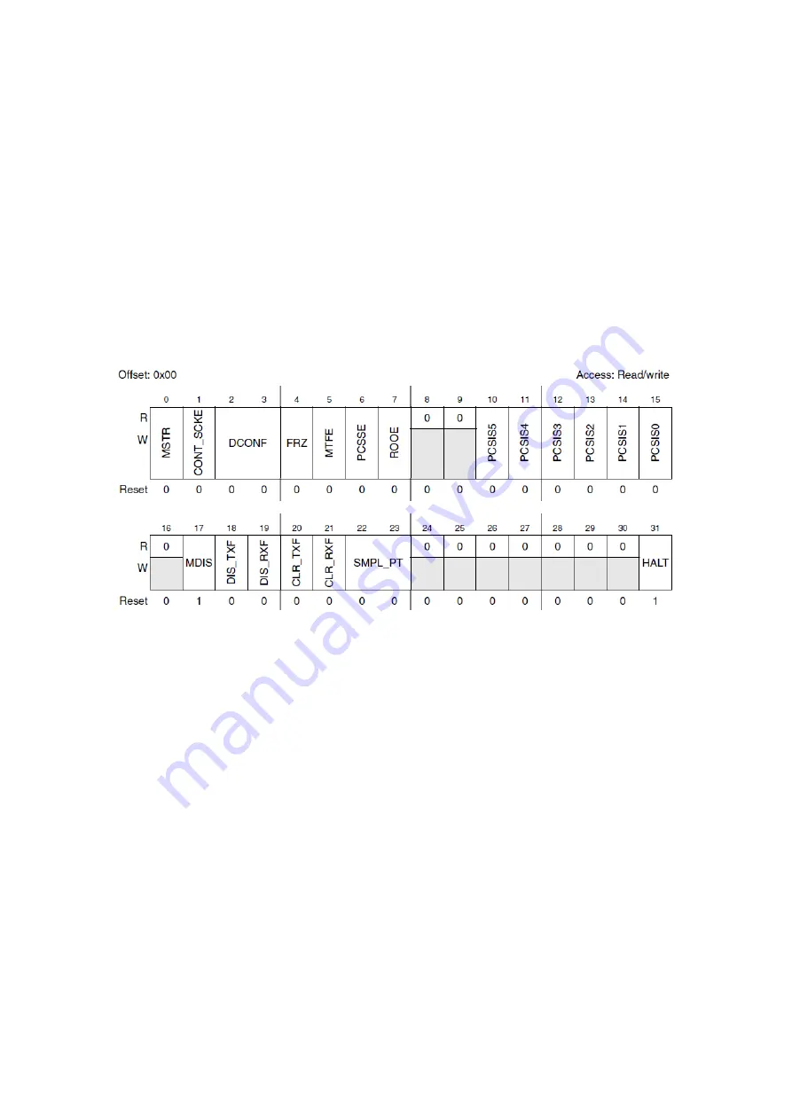
Figure 89 : DSPI Module Configuration Register (R.M. Rev8 –Fig. 23-3)
This configuration register has the following fields:
MSTR: Master/slave mode select (‘1’ for master),
CONT_SCKE: Continuous SCK enable (see below more details),
FRZ: Freeze, when the device enters debug mode, DSPI transfers halt at the next frame
boundary,
MTFE: Modified timing format enable (see below for more details),
PCSSE (Peripheral Chip Select Strobe Enable): when enabled CS5 signal can be used on
an demultiplexer to decode the CS signals into as much as 32 glitch-free CS signals. It
introduces a delay before and after the frame, allowing for the switching of CS[0:4] on
the demultiplexer to avoid glitches output. See Transfer Configuration Register for
setting these delays.
ROOE: Receive FIFO overflow overwrite enable. If cleared, the incoming data is ignored
when FIFO is full, when set, the incoming data is put in the shift register.
PCSISx; Peripheral chip select inactive state, if cleared, the inactive state is low, is set, the
inactive state is high. In slave mode, it has to be set as inactive high (common in SPI).
MDIS: Module Disable: When set, disable DSPI clocks to save power.
DIS_TXF: Disable transmit FIFO buffer. Similarly with DIS_RXF for receive FIFO.
CLR_TXF: Clear transmit FIFO, reset its counter. Similarly with CLR_RXF for receive FIFO.
Содержание MPC5604B
Страница 1: ...LAAS CNRS Quick Start to MPC5604B Embedded Development Sahin Serdar 21 06 2013...
Страница 31: ...Figure 33 INTC SW HW mode comparison Freescale Tutorial...
Страница 87: ......
Страница 132: ......
Страница 133: ...127 Appendix 2 Pad Configurations...
Страница 134: ......
Страница 135: ......
Страница 136: ......
Страница 137: ......
Страница 138: ......
Страница 139: ......
Страница 140: ......
Страница 141: ...Appendix 3 Peripheral input pin selection...
Страница 142: ......
Страница 143: ...137 Appendix 4 Interrupt Vector Table...
Страница 144: ......
Страница 145: ......
Страница 146: ......
Страница 147: ......
Страница 148: ...Appendix 5 I C Baud Rate Prescaler Values...
Страница 149: ......
Страница 150: ......


