


1.5.
Bit-rate and sampling
CAN controllers have a system clock that allow them to process registers, set outputs and read
inputs. The period duration of this clock is called the time quantum
𝑇
𝑞
and used as a base to
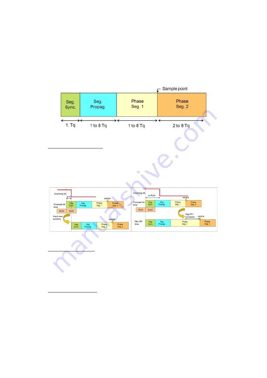
transmit and receive frames. A bit-time is built of four time segments, each defined by an integer
number of time quantum. These segments allow the receiver to synchronise before sampling a
bit, minimising chances of misread data. The bit time also determines the bit-rate of the
network.
Figure 115: Bit-time structure
Synchronisation segment: always equal to one time quantum, rising/falling edge of the
incoming bit has to be before a forecast time of this segment. In practice this rarely
happens, so the standard tries different way to synchronise by changing the length of
different segments, or delaying them, depending on a value called
RJW(Resynchronization jump width). These methods are illustrated on the following
figure.
Figure 116: Bit-time resynchronisation methods
Propagation segment: Takes in account the delay due to the propagation speed of the
CAN signals. CAN standard suggests considering the worst case situation where a device
emits recessive bit and just before this bit reaches its destination, the other device emits
a dominant bit. Therefore the total delay becomes the round trip time of the signal
2*(2.
𝑇
𝑐𝑜𝑛𝑡𝑟𝑜𝑙𝑙𝑒𝑟
𝑑𝑒𝑙𝑎𝑦
+ 2.
𝑇
𝑡𝑟𝑎𝑛𝑠𝑐𝑖𝑒𝑣𝑒𝑟
𝑑𝑒𝑙𝑎𝑦
+
𝑇
𝑏𝑢𝑠
𝑑𝑒𝑙𝑎𝑦
). Propagation segment has to be
greater than this value.
Phase segments 1&2: Phase segment 2 should not be shorter than CAN controller’s
information processing time(IPT
≤
2
𝑇
𝑞
usually) and depending on number of quanta in
the bit time we can have Phase_Seg_1 = Phase_Seg_2 or Phase_Seg_2 = Phase 1;
Depending on these values, a CAN bus’ efficiency can change a lot, an effective method for
calculating these values is:
Finding the total delay explained above, either with device datasheet or measurements.
Selecting a frequency for CAN Controller clock and a bit-rate meeting the specifications.
Содержание MPC5604B
Страница 1: ...LAAS CNRS Quick Start to MPC5604B Embedded Development Sahin Serdar 21 06 2013...
Страница 31: ...Figure 33 INTC SW HW mode comparison Freescale Tutorial...
Страница 87: ......
Страница 132: ......
Страница 133: ...127 Appendix 2 Pad Configurations...
Страница 134: ......
Страница 135: ......
Страница 136: ......
Страница 137: ......
Страница 138: ......
Страница 139: ......
Страница 140: ......
Страница 141: ...Appendix 3 Peripheral input pin selection...
Страница 142: ......
Страница 143: ...137 Appendix 4 Interrupt Vector Table...
Страница 144: ......
Страница 145: ......
Страница 146: ......
Страница 147: ......
Страница 148: ...Appendix 5 I C Baud Rate Prescaler Values...
Страница 149: ......
Страница 150: ......


