


Underload Sensitivity Selection – SubDrive75/100/150
The SubDrive controller is configured at the factory to ensure
detection of Underload faults in a wide variety of pumping
applications. In rare cases (as with certain pumps in shallow
wells) this trip level may result in nuisance faults. If the pump is
installed in a shallow well, activate the controller and observe
system behavior. Once the controller begins to regulate
pressure, check operation at several flow rates to make sure
the default sensitivity does not induce nuisance Underload
trips.
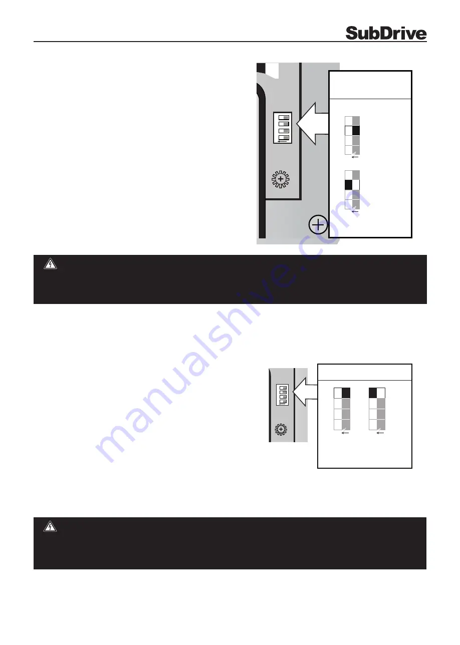
If it becomes necessary to desensitize the Underload trip level,
remove power and allow the controller to discharge. Once the
internal voltages have dissipated, locate the DIP switch marked
“SW1” at the lower right corner of the main circuit board. Use a
small screwdriver (provided) to change Position 3 to the “ON”
position to select the lower Underload sensitivity as shown in
the chart below.
Serious or fatal electrical shock may result from contact with internal electrical components. DO NOT, under any
circumstances, attempt to modify DIP switch settings until power has been removed and 5 minutes have passed
for internal voltages to discharge! Power must be removed for DIP switch setting to take effect.
DANGER
Steady Flow Selection
SubDrive75/100/150
The SubDrive/MonoDrive controller is configured at the factory to
ensure quick response to maintain constant pressure. In rare cases
(as with a water line tap before the pressure tank), the controller
may need to be adjusted to offer better control.
If the controller is used on a system that has a water line tapped
before the pressure tank and close to the well head or where
audible speed variations of the PMA can be heard through the
pipes, adjusting the pressure control response time may be
necessary. After enabling this feature, the installer should check
flow changes for possible overshoot. A larger pressure tank and/
or wider margin between regulation and valve pressure may
be required as the Steady Flow features reduce the controller’s
reaction time to sudden changes in flow.
If it is necessary to adjust the pressure control, remove power and
allow the controller to discharge. Wait 5 minutes to allow internal voltage to dissipate, locate the DIP switch marked
“SW1”. Use a small screwdriver (provided) to move position 4 to “ON” as shown.
ON
1
2
3
4
SW1
Configuration Switch SW1
1
2
3
4
O N
1
2
3
4
O N
Normal
(default)
Steady Flow
1
2
3
SubDrive
ON
1
2
3
4
SW1
Configuration
Switch SW1
1
2
3
4
O N
1
2
3
4
O N
Normal (default)
Low (shallow wells)
9
Technical changes without notice / Techn. Änderungen vorbehalten / Modifications techniques réservées sans préavis / 5930


