background image

Electric Ignition 

The electric ignition system operates by heating a ceramic electric heating element positioned 2mm from the bottom 
of the burner. Oil entering the burner is heated to its ignition temperature by the heating element. The element is 
energised for the period that the ignition button is pressed, between 30 seconds and a minute. 
 

Common reasons for ignition to fail 

Electrical cable not connected. 
Oil supply switched off. 
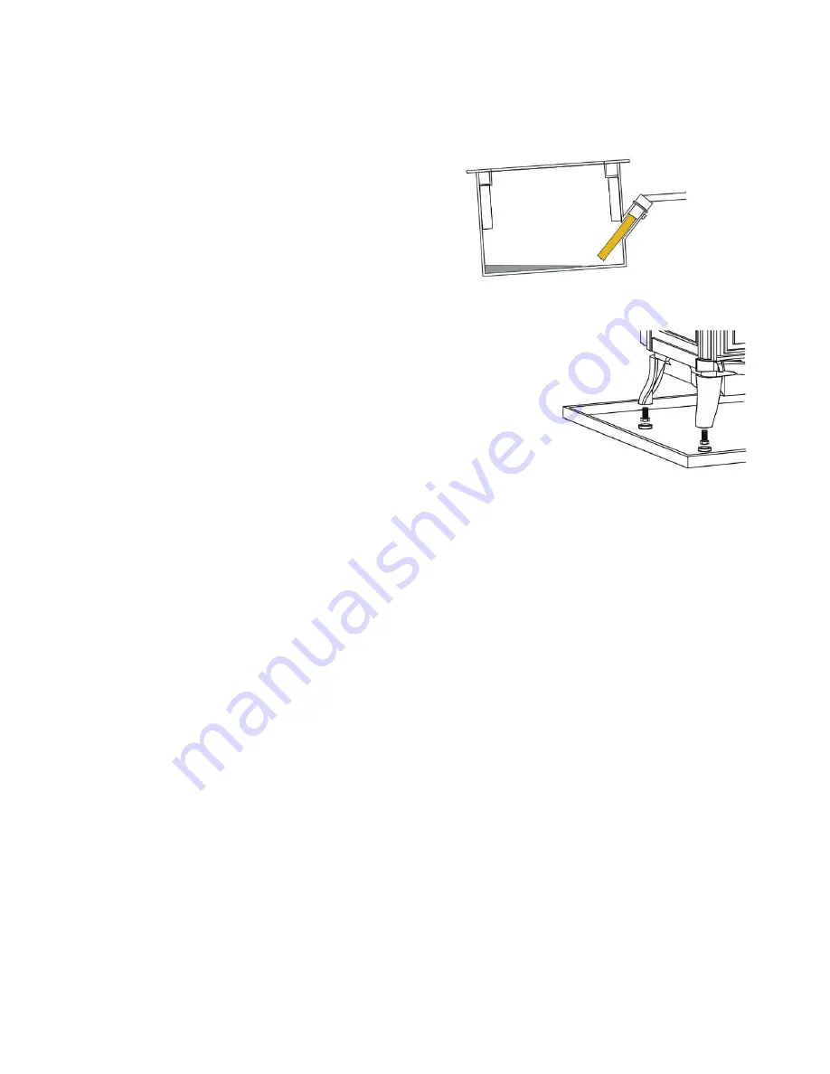
Burner has large amount of oil in the base. 
Stove not level. 
Igniter leads at the control box poorly connected. 
Ceramic element touching the base of the burner. 
 

Stove and burner must be level 
 

If  the  oil  burner  is  not  level  as  oil  enters  for  ignition  it  will  flow  away  from  the 
igniter. This oil will build up until it finally reaches the igniter. This will result in long 
ignition times and excessive oil at ignition. 
Adjust the levelling feet in the legs of the stove. 
 
Excessive oil will cause large flames, soot and very noisy operation. 


Oil Metering Valve 

The oil metering valve is set to give the correct flow rates before being fitted to the stove and will not normally require 
further adjustment. Any but a small adjustment should be regarded as an indication of a fault of the fuel supply, or of 
a flue system giving an incorrect negative pressure within the stove, and these should be examined thoroughly before 
attempting to re-calibrate the oil metering valve. 
The oil metering valve performs three operations within its main body; it regulates with a float valve the depth of oil 
held, it meters with an adjustable outlet the fuel supplied to the burner, and its safety float valve will isolate the fuel 
should the levels within the valve body become too high. 

The safety float will cause the arming lever to “trip” whenever the fuel levels become too high, but

 severe vibration 

can cause ripples on the fuel surface to lift the float, and because of this it is possible for the vibration set up by heavy 
passing traffic to shut off the valve. 

Having “tripped”, resetting the arming lever may need to be done several times 

before the fuel level within the valve falls sufficiently to allow reliable operation. 
The firing rate of the burner is regulated by the oil metering valve and having set the extremes of low and high firing 
as detailed in the commissioning instructions, the firing rates are proportioned as indicated by the indices 1-6 on the 
valve top when aligned to by the control knob. 
 

Most common problems 

The oil control is a very reliable control system. If a problem with the oil flow is suspected it is very unlikely to be the 
control valve. 
 
The most common reason for poor flow rates will be air trapped within the oil supply pipe or the oil valve float control 
stem. If an air lock is suspected the oil line should be disconnected from the oil valve and at least 1 litre of oil allowed 
to flow after no air is present. 
 
If an air lock is suspected in the oil control valve, remove the top plate mounting screws and press the float assembly 
to the base of the oil control for 4-5 seconds, this will fully open the oil level inlet needle releasing trapped air. 


Содержание Burgundy

Страница 1: ...TECHNICAL ABGO 1 SIDINGS CLOSE WEDNESFIELD ROAD WOLVERHAMPTON WV11 3DR Oil Stove Installation INSTRUCTIONS FOR FRANCO BELGE OIL STOVES...

Страница 2: ...e publications may be superseded during the life of this manual BS 799 Part Five Specification for Oil Tanks BS 5410 Part One Oil Firing Installations Up To 44kW BS 4543 Parts One Three Factory Made I...

Страница 3: ...d Installation Commissioning and Servicing Technicians and Tank Installation Technicians from the need to give notice and pay a fee when carrying out new installation work replacement work or making a...

Страница 4: ...ote acting fire valves and major changes to flueing systems Part L1 of the Regulations which came into force at the same time covers the energy efficiency aspects of heating system installation partic...

Страница 5: ...plate 5 and the clamp 4 from the back and refit them on the top with the 2 screws and washers supplied 7 ensuring there is a good seal 2 Set the ceramic rope in the groove and fix the flue collar at r...

Страница 6: ...the requirements of Building Regulations and providing suitable access to facilitate servicing the stove providing a setting which will complement the stove is not a luxury it is the practicality of m...

Страница 7: ...ss required for installation This is the minimum distance in front at floor level from the base of the stove All combustible materials above floor level in front of the appliance must be a minimum dis...

Страница 8: ...f this heat by being constructed with an internal surface as smooth as possible and by being thermally insulated Both these requirements can be met in an existing chimney by lining it with a stainless...

Страница 9: ...ue shall have no more than four bends each providing a maximum change of direction of 45 there should be not more than two of these bends before an access point for sweeping and two between a sweeping...

Страница 10: ...e anti down draught cowls work by inducing up draught which can seriously affect the combustion within the burner and may even cause damage to the catalyser It is as important to fit the cowl correctl...

Страница 11: ...A metal bowl oil filter mounted to allow adequate room for the removal of the sediment bowl and filter element without difficulty should be fitted in the pipeline to the property We recommend a repla...

Страница 12: ...in its main body it regulates with a float valve the depth of oil held it meters with an adjustable outlet the fuel supplied to the burner and its safety float valve will isolate the fuel should the l...

Страница 13: ...Toby valve CI valve...

Страница 14: ...ill give the actual pressure within the stove but it is not possible to verify the pressures to enable the correct adjustment of the draught stabilizer without a suitable manometer The pressure must b...

Страница 15: ...Draught Requirements Burgundy 0 075inches WG 17 Pa 0 035 inches WG 8 Pa Note This is not a water gauge used to measure gas pressure Minimum Maximum Inches water gauge...

Страница 16: ...ions The customers who will operate the stove are an essential component of any installation Ensuring they understand the operation of the stove its controls and what to expect from the installation w...

Страница 17: ...e stove and flue warm the supply of air being induced into the burner will increase and it will be possible to raise the stove s firing rate progressively until the stove is running at its maximum out...

Страница 18: ...inutes should be allowed for the flue draft to stabilise after adjusting the flue stabilizer Low Fire Minimum flame size Flue draught set at the requirement for low fire No 1 setting e g 0 04 wg The c...

Страница 19: ...ases of draught from external conditions such as wind If this is the case the flue termination position must be examined to confirm it is correct and a draught stabilising cowl fitted 2 Excessive nega...

Страница 20: ...Advise the customer that if the stove is to be out of operation for more than a few weeks that the isolation tap which should be located by the stove should be turned off demonstrate this to the custo...

Страница 21: ...Fault Finding Flow Charts...

Страница 22: ...Check continuity of igniter Replace igniter if defective Is igniter 2mm from burner floor Adjust igniter to 2mm above burner floor Has oil reached area below igniter...

Страница 23: ...Dwyer 460 flue draught gauge recommended Flame burning only from inlet port...

Страница 24: ...Fit a stabilizing cowl and or Secondary draught stabilizer Fit a secondary draught stabilizer Adjust draught stabilizer Direct heat from heater or hair drier into stove Balance draught stabilizer agai...

Страница 25: ......

Страница 26: ...n good condition replace if damaged or hard 13 Using a vacuum cleaner remove dust dog and cat hairs and any cobwebs from behind the stove that could be a fire hazard 14 Reassemble the stove and light...

Страница 27: ...Service Record Year Date Company Engineer Tel No Parts replaced 1 2 3 4 5 6 7 8 9 10...

Страница 28: ...ppliances without prior notice We make every effort to ensure that the information provided in this document is correct and accurate at the time of printing We would request that you inform ABGO of in...

Отзывы: