25
Chapter 2 Installation Instructions
875A02 User Manual
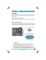
SIDE (Secondary IDE Interface)
PIDE(Primary IDE
Interface)
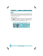
Front Panel Connector: FP1
This motherboard includes one connector for connecting the front panel
switch and LED indicator.
HD_LED Connector
Attach the connector to the HD_LED on the front panel of the case; the LED
will flash while the HDD is in operation.
Reset Switch
Attach the connector to the Reset switch on the front panel of the case; the
system will restart when the switch is pressed.
Power LED Connector
Attach the connector to the power LED on the front panel of the case. The
Power LED indicates the power supply status, and will be lit during normal
system operation. The Power LED will blink while the system is in the S1
mode, and will be turned off when the system is in either S3 or S5 mode.
NC
HD_LED
R S T
P L E D
PBTN
+
-
9 10
1 2
GND
GND
Key
+
-
Содержание 875A02
Страница 8: ...This page is intentionally left blank 875A02 English preface V1 0 010604 p65 2004 4 12 13 39 8 ...
Страница 13: ...5 Chapter 1 Product Introduction 875A02 User Manual 875A02 Layout 16 17 18 2 4 1 5 6 7 14 15 10 8 3 11 9 13 12 ...
Страница 100: ...92 875A02 User Manual Chapter 5 Directions for Bundled Software 3 Click Update 4 Click Yes ...
Страница 103: ...95 875A02 User Manual Chapter 5 Directions for Bundled Software 3 Click Ok to update BIOS 4 Click Restart ...


