background image

Page 4

OPERATING INSTRUCTIONS

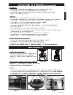
Release Tank Pressure

Pressure Release Valve (PRV) on select models

1. 

NO PRV:  

Lay the tank on its side with the hose

    outlet on the bottom. Direct the nozzle away

    from you and squeeze the shut-off lever until

    the unit stops spraying. 

(See Figure I)

2. 

WITH PRV:

 Pull up on the knob of the PRV until

    all pressure is released from the tank. 

    (See Figure J)

Filling

IMPORTANT: Always make sure the pressure is

released from the tank before filling or servicing. 

If equipped, pull up on the knob of the pressure 

release valve until all the pressure is released 

from the tank. Otherwise, squeeze and hold

shut-off lever until the unit stops spraying. Then, 

and only then, it is safe to remove pump.

1. Turn the pump handle counterclockwise to remove

    the pump 

(See Figure E).

2. Fill the tank to the desired level. See fill markings

    on side of tank. (Always refer to chemical

    manufacturer for proper mixture).

3. Install the pump into the tank opening and turn

    clockwise until tightly sealed against the tank


(See Figure F).

Figure F

Figure E

Pressurizing

1. Make sure shut-off lock is not engaged. (If shut-off lock is engaged while pressurizing, the unit 

    will immediately start spraying).

2. Push down on the handle and turn counterclockwise to unlock the handle 

(See Figure G-1G)

.

3. Pressurize the sprayer by pumping the handle in a smooth up and down motion 

(See Figure G-2G)

.

4. Push down on the handle and turn clockwise to lock the handle into the pump 

(See Figure G-3G)

.

Figure G

1G

2G

3G

Figure J

Figure I

Spraying and Locking

1. Direct nozzle away from you and squeeze shut-off

     lever to begin spraying.

2. For continuous spraying, squeeze lever and rotate

     lock 

(See Figure H)

.

3. Unlock if needed and release shut-off lever to stop

    spraying.

4. Turn the nozzle tip to adjust the spray pattern.

Figure H

LEVER

Содержание D.B.Smith

Страница 1: ...r To The Store For Help Information or Parts Call 1 800 311 9903 The Fountainhead Group Inc 23 Garden St New York Mills NY 13417 1 800 311 9903 www TheFountainheadGroup com CAUTION Read and follow all instructions Use and Care Manual D B Smith Professional Series Sprayers O Style R Style ...

Страница 2: ... Always release pressure when sprayer is not in use and before removing pump from tank Do not stand with face or body over top of tank when pumping or loosening pump to prevent pump or solution from striking you resulting in serious injury Clean and rinse sprayer thoroughly after each use Never attempt to alter sprayer from original condition Always use replacement parts from original manufacturer...

Страница 3: ...ustable Cone Nozzle D Red High Volume Fan Nozzle E Yellow Low Volume Fan Nozzle F Flat Seal G Adapter H Extension C A G B D F H E ADJUSTABLE CONE USES Spot spraying in or around flower beds trees and shrubs Edging along fences driveways and walkways Killing brush such as poison ivy poison oak kudzu and wild blackberry Preparing garden beds for planting of ornamentals and vegetables For precision s...

Страница 4: ... to the desired level See fill markings on side of tank Always refer to chemical manufacturer for proper mixture 3 Install the pump into the tank opening and turn clockwise until tightly sealed against the tank See Figure F Figure F Figure E Pressurizing 1 Make sure shut off lock is not engaged If shut off lock is engaged while pressurizing the unit will immediately start spraying 2 Push down on t...

Страница 5: ...ressurizing section 8 Direct the nozzle away from you and activate the shut off for at least 30 seconds to clean the hose and shut off 9 Release pressure as described in the Release Tank Pressure section 10 Remove the pump and empty the contents into gravel or bare soil 11 Repeat steps 5 10 until thoroughly cleaned Finish 1 Depressurize the tank as described in Release Tank Pressure section 2 Turn...

Страница 6: ...e cap securely turn the barrel clockwise to lock the tabs in place Figure 5 R Style 1 Inspect gasket If worn or damaged remove and replace See Figure 6 2 To remove pump cap from pump barrel remove screws securing pump cap to barrel See Figure 7 3 Inspect o ring If worn or damaged remove and replace Lubricate o ring with petroleum jelly See Figure 8 4 Inspect check valve in bottom of barrel If worn...

Страница 7: ...tion 4 Replace if worn or damaged as described in Pump Disassembly Reassembly section Sprayer material overflows through pump barrel or pump handle rises when handle is unlocked 1 Dirt or debris under check valve 2G 5H or 6A on pump 2 Chipped torn or swollen pump check valve 2G 5H or 6A 1 Clean check valve 2G 5H or 6A and valve sealing surface on pump 2 Replace check valve 2G 5H or 6A as described...

Страница 8: ... 2A 2C 2E 2F 2G 1 1 1 2 1 3 2D KIT 2 5B 5A 5C 5D 5F 5G 5H 4 5E 3 2 3 3 KIT 5 9A 9F 10F 10B 10D KIT 9 KIT 10 7 21 7 18 11A KIT 11 11G 11F 11E 11D 11B 9B 9E 9C 9D 11C 10E 10C 10A 8 1 8 3 8 2 11E 11F 11C 11D 11A 11B R O 7 SS 6A 6B 6C KIT 6 6C ...

Страница 9: ...II SS 182112 21 EXTENSION ASSEMBLY STAINLESS STEEL SMITH PRO II 1 181817 SHUT OFF ASSEMBLY SMITH PRO II 1 GAL 2 181818 SHUT OFF ASSEMBLY SMITH PRO II 2 GAL 3 181819 SHUT OFF ASSEMBLY SMITH PRO II 3 GAL KIT 11 181910 SMITH PRO II SHUT OFF SERVICE KIT 11A 181493 VALVE BODY O RING 11B 181840 POPPET SEAL 11C 181231 BARB O RING 11D 181468 FILTER 11E 181812 FLAT NOZZLE SEAL 2 11F 181810 WAND O RING 11G ...

Страница 10: ...SSORIES ARE AVAILABLE BY CONTACTING The Fountainhead Group Inc Customer Service Center Monday Friday 8 A M 5 P M EST Toll Free 1 800 311 9903 or e mail Info TheFGI com or Access online at www TheFountainheadGroup com Page 10 ...

Страница 11: ... ayuda información o piezas llame al 1 800 311 9903 The Fountainhead Group Inc 23 Garden St New York Mills NY 13417 1 800 311 9903 www TheFountainheadGroup com PRECAUCIÓN Lea y siga todos las instrucciones Estilo O Estilo R Manual de uso y cuidado D B Atomizadores de la Serie Profesional Smith ...

Страница 12: ...s Sólo use la bomba original No almacene sustancias químicas en este tanque Siempre alivie la presión cuando el rociador no está en uso y antes de quitar la bomba del tanque No se pare con lacara o el cuerpo sobre la parte superior del tanque cuando bombea o afloja la bomba para evitar que la bomba o la solución le haga contacto con su querpo resultando en lesión grave Limpie y enjuague el atomiza...

Страница 13: ...ara espuma C Boquilla de cono adjustable D Boquilla roja con ventilador para alto volumen E Boquilla amarilla con ventilador para bajo volumen F Sello plano G Adaptador H Extensión C A G B D F H E Usos de las boquillas cono ajustables Rociado localizado en o alrededor de arriates árboles o arbustos Bordes a lo largo de cercas entradas y caminos Destrucción de malezas por ejemplo hiedra venenosa ro...

Страница 14: ...hacia abajo el mango y gírelo en sentido antihorario para destrabar el mango Vea la Figura G 1G 3 Presurice el atomizador bombeando el mango con un movimiento uniforme hacia arriba y hacia abajo Vea la Figura G 2G 4 Empuje el mango hacia abajo y gírelo en sentido horario para trabar el mango en la bomba Vea la Figura G 3G Figura G 1G 2G 3G Libere la presión del tanque Válvula de liberación de pres...

Страница 15: ...n sentido antihorario para quitar la bomba 3 Vacíe todo el líquido restante de acuerdo con las intrucciones de desecho del producto 4 Siga las instrucciones de Limpieza INSTRUCCIONES DE OPERACIÓN continuación Alamacenamiento del atomizador 1 El tanque del atomizador debe colgarse en posición invertida y sin la bomba 2 No almacene ni deje solución dentro del tanque después del uso 3 Guárdelo en un ...

Страница 16: ...llas en su lugar Estilo R 1 Inspeccione la empaquetadura Si está gastada o dañada sáquela y reemplácela Vea la Figura 6 2 Para sacar la tapa de la bomba del cilindro de la bomba retire los tornillos que aseguran la tapa de la bomba al tubo Vea la Figura 7 3 Inspeccione la junta tórica Si está gastada o dañada sáquela y reemplácela Lubrique la junta tórica con gel de petróleo Vea la Figura 8 4 Insp...

Страница 17: ...uelta 2 Manguera agrietada dilatada o defectuosa 1 Ajuste la tuerca de manguera 2 Reemplace el conjunto de cierre Atomizador difícil de bombear 1 La junta tórica del pistón No 2D o No 6C está dañada 2 La junta tórica del pistón No 2D o No 6C está seca 1 Reemplace la junta tórica del pistón come se describe en la sección Desensamblar y volver a ensamblar la bomba 2 Lubrique la junta tórica del pist...

Страница 18: ...2C 2E 2F 2G 1 1 1 2 1 3 2D KIT No 2 5B 5A 5C 5D 5F 5G 5H 4 5E 3 2 3 3 KIT No 5 9A 9F 10F 10B 10D KIT No 9 KIT No 10 7 21 7 18 11A KIT No 11 11G 11F 11E 11D 11B 9B 9E 9C 9D 11C 10E 10C 10A 8 1 8 3 8 2 11E 11F 11C 11D 11A 11B R O 7 SS 6A 6B 6C KIT 6 6C ...

Страница 19: ...SMITH PRO II 18 181843 ENSAMBLADO DE LA EXTENSIÓN DE 18 SMITH PRO II 21 181824 ENSAMBLADO DE LA EXTENSIÓN DE 21 SMITH PRO II SS 182112 ENSAMBLADO DE LA EXTENSIÓN DE 21 ACERO INOXIDABLE SMITH PRO II 1 181817 ENSAMBLADO DEL CIERRE SMITH PRO II 1 GALÓN 2 181818 ENSAMBLADO DEL CIERRE SMITH PRO II 2 GALONES 3 181819 ENSAMBLADO DEL CIERRE SMITH PRO II 3 GALONES KIT No 11 181910 JUEGO DE MANTENIMIENTO DE...

Страница 20: ...E ENCUENTRAN DISPONIBLES COMUNICÁNDOSE A The Fountainhead Group Inc Centro deservicio al cliente De lunes a viernes de 8 A M a 5 P M EST Llame sin costo al 1 800 311 9903 o Correo electrónico Info TheFGI com o Ingrese en línea a www TheFountainheadGroup com ...

Отзывы: