8
VM04 Owner’s manual
INPUT
-10
-50
TRIM
TRIM
-10
-50
3
2
1
4
OUTPUT
L
R
MIN
MAX
PHONES
FOOT SW
OUT
S/P DIF
9V
DC IN
RESET
1 2
3
4
5
6
7
8
9
10
12
11
13
14
15
16
17
18
19
20
21
22
23 24
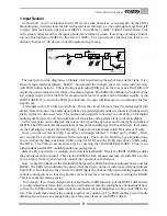
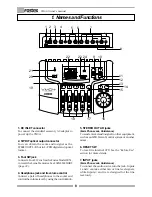
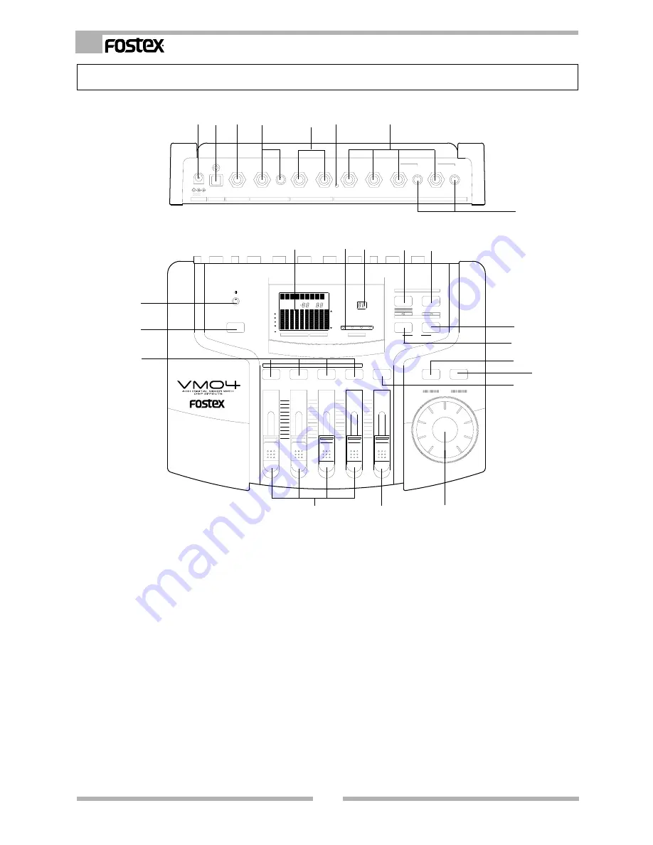
1. DC INLET connector
To connect the standard accessory AC adaptor to
power up the VM04.
2. S/P DIF optical output connector
You can obtain the same audio signal as the
STEREO OUT L/R, but in S/P DIF digital and optical
format.
3. Foot SW jack
Connect a Foot SW, such as the Fostex Model 8051,
to recall the Scene Memories. See SCENE MEMORY
(page 22).
4. Headphone jack and its volume control
Connect a pair of headphones to the socket and
control the volume level by using the control knob.
1. Names and Functions
5. STEREO OUT L/R jacks
(6mm Phone Jack, Un-Balance)
To send a mixed audio signal to other equipment,
such as an MTR, Stereo Monitor system or another
mixer.
6. RESET SW
To reset the internal CPU. See the “Before Use”
section for more details.
7. INPUT jacks
(6mm Phone Jack, Un-Balance)
To connect the audio source into the jack. Inputs
1 and 2 can take either mic or line level signals,
while Inputs 3 and 4 are designed for the line
level only.
EQ
VIEW
CHANNEL EDIT
MASTER
4
3
2
1
MAX
MIN
SCENE No
0
6
12
24
OL
1
2
3
4
L
R
1
2
3
4
MIN
R
MAX
EFF
HI
LO
PAN
EQ
VIEW
LEVEL
FADER ADJUST
ENTER
EXIT
DATA
STORE
RECALL
SCENE
PARAMETER
TYPE
EFFECT
SETUP
MAX
MIN
MAX
MIN
MAX
MIN
CH
MASTER
48
L


