


Hardware Setup
Hardware Setup
Unpack and power up the appliance(s) as described in the Hardware Setup Guide included with
the appliance. For some appliances, the power supply fan goes on when the appliance is first
plugged in.
Note:
On some appliances the power switch is located behind the bezel on the front of the
machine. Be sure to remove the bezel and power up the appliance first.
DO NOT CONNECT THE APPLIANCE(S) TO THE NETWORK AT THIS TIME.
Connect To The Appliance
1.
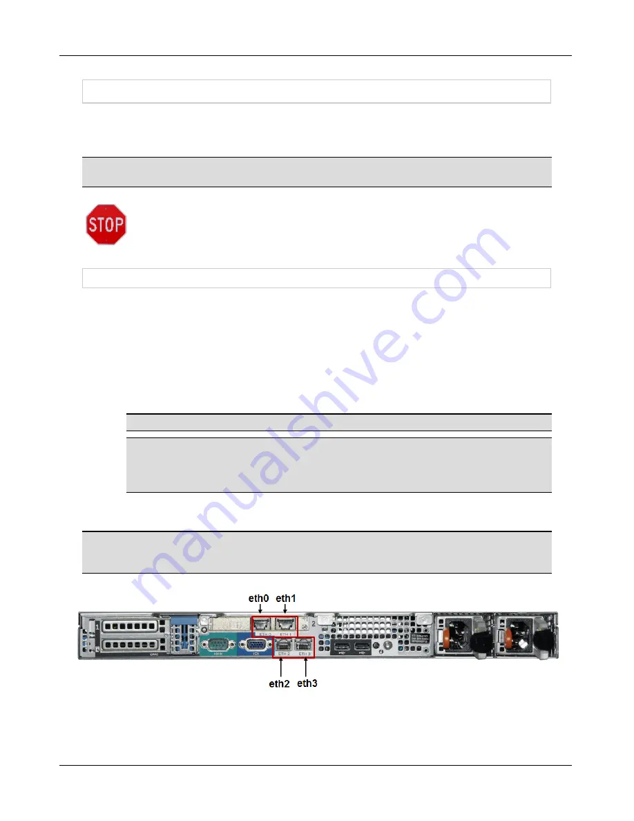
See Figures 1 through 7. Note that the port etched with number 1 is eth0 and the port
etched with number 2 is eth1 or the left most port is eth0 and the next port to the right is
eth1.
2.
Use either a straight-through or crossover RJ45 cable to connect your PC to eth1 of the
appliance. Port eth1 serves DHCP in the 192.168.1.x range. The appliance itself has an
IP address of 192.168.1.1. Be certain to connect the RJ45 cable to the correct Ethernet
port. LED 1 on the front of the appliance lights to indicate when eth0 has established
connection. LED 2 lights to indicate when eth1 has established connection.
Note:
Not all models of the appliance have LED lights on the front.
Note:
When a FortiNac Control Server and Application Server are paired, configure the
FortiNac Application Server hardware first to assign an IP address. The FortiNac
Control Server must know the IP address of the FortiNac Application Server in order to
communicate with it.
3.
On the PC, bring up a web browser. To launch the Configuration Wizard, navigate to:
http://192.168.1.1:8080/configWizard
Note:
Appliances have a LCD panel on the front that displays the Appliance Type, such as
FortiNac Control Server, and the FortiNac Version number installed. This information does not
display until the FortiNac software is started.
Figure 1: Appliance BFN320
6
Содержание FortiNac BFN320
Страница 1: ...Appliance Installation Guide Version 8 3 Date 8 24 2018...
Страница 7: ...4...
Страница 11: ...Hardware Setup Note You will be required to change the Configuration Wizard password during the setup process 8...
Страница 19: ...Software Configuration Figure 7 Download Documentation Window 16...
Страница 20: ...Password Setup Figure 8 Change Passwords Figure 9 Configuration Wizard Password Setup Password Setup 17...
Страница 22: ...7 Close the window or tab 8 Click Next to continue Password Setup 19...
Страница 27: ...Layer 2 Network Configure VLANS Figure 11 Layer 2 Isolation Figure 12 Add Subnet 24...
Страница 35: ...Layer 3 Network Configure Route Scopes Figure 15 Layer 3 Network Configuration Isolation Scopes 32...
Страница 39: ...Layer 3 Network Configure Route Scopes Figure 18 Layer 3 Access Point Management 36...
Страница 40: ...Figure 19 Layer 3 Add Access Point Management Scopes Layer 3 Network Configure Route Scopes 37...
Страница 42: ...Figure 20 Layer 3 Routes Import Route Scopes Window Layer 3 Network Configure Route Scopes 39...
Страница 44: ...Figure 21 Additional Routes Window Figure 22 Add Route Window Layer 3 Network Additional Routes 41...
Страница 46: ...Figure 23 Results Window Results Layer 2 Layer3 Networks Or Control Manager 43...
Страница 49: ...Change Passwords After Configuration 46...


