


FortiGate-7060E chassis
Fortinet Technologies Inc.
Connecting the FortiGate-7060E chassis to ground
The FortiGate-7060E chassis includes a ground terminal on the rear the bottom of the FortiGate-7060E back panel. The
ground terminal provides two connectors to be used with a double-holed lug such as Thomas & Betts PN 54850BE. This
connector must be connected to a local ground connection.
You need the following equipment to connect the FortiGate-7060E chassis to ground:
l
An electrostatic discharge (ESD) preventive wrist strap with connection cord.
l
One green 6 AWG stranded wire with listed closed loop double-hole lug suitable for minimum 6 AWG copper wire,
such as Thomas & Betts PN 54850BE.
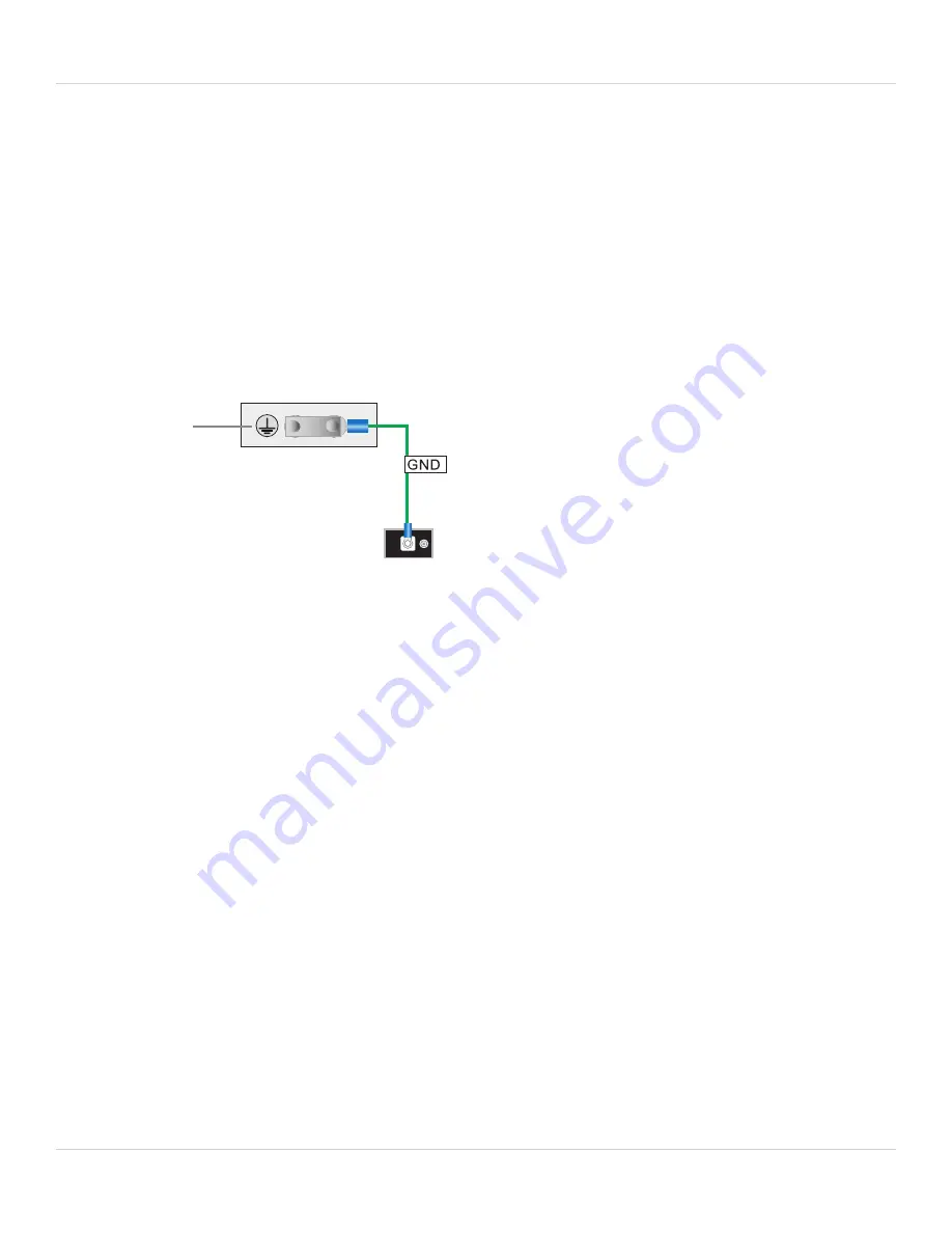
To connect the FortiGate-7060E chassis to ground
Data Center
ground
connector
(Central office
ground system)
Chassis
Ground
Connector
1.
Attach the ESD wrist strap to your wrist and to an ESD socket or to a bare metal surface on the chassis or frame.
2.
Make sure that the chassis and ground wire are not energized.
3.
Connect the green ground wire from the local ground to the ground connector on the FortiGate-7060E chassis.
4.
Secure the ground wire to the chassis.
5.
Optionally label the wire GND.
Turning on FortiGate-7060E chassis power
Connect AC or DC power to PSUs 1, 2, 3, and 4. Once the FortiGate-7060E chassis is connected to power the chassis
powers up. If the chassis is operating correctly, the LEDs on the PSUs and fans should be lit. As well, the LEDs on the
SMMs should be lit.
When the chassis first starts up you should also hear the cooling fans operating.
In addition, if any modules have been installed in the chassis they should power on and their front panel LEDs should
indicate that they are starting up and operating normally.
FortiGate-7060E 6.4.2 System Guide
23


