vi
ModuSys 2000 Kernel
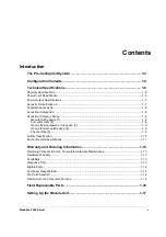
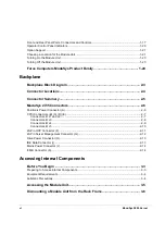
Front and Rear Panel Ports, Connectors and Controls .................................................................1-17
Operator Control Panel Indicators .................................................................................................1-20
Option Support ...............................................................................................................................1-21
Choosing a Location for the Module Unit.......................................................................................1-21
Turning On the Module Unit ...........................................................................................................1-23
Turning Off the Module Unit ...........................................................................................................1-23
Force Computers ModuSys Product Family ................................................. 1-24
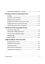
Backplane
Backplane Block Diagram ................................................................................ 2-3
Connector Locations......................................................................................... 2-4
Connector Summary ......................................................................................... 2-5
ModuSys 2735 Connectors............................................................................... 2-6
Positronic Power Connector (A).......................................................................................................2-6
CPCI Connectors (B) (C) (D) (E)......................................................................................................2-7
Connectors B; J1 and J2.............................................................................................................2-7
Connectors B; J3 ........................................................................................................................2-8
Connectors B; J4 ........................................................................................................................2-9
Connectors B; J5 ......................................................................................................................2-10
20-Pin OCP Connector (F).............................................................................................................2-11
20-Pin Server Management Connector (G) ...................................................................................2-12
Drive Power Connector (H) ............................................................................................................2-13
IDE Data Connector (I)...................................................................................................................2-13
Mains Power Connector (J)............................................................................................................2-14
ICMB Connector (K) .......................................................................................................................2-14
Accessing Internal Components
Before You Begin .............................................................................................. 3-3
Preparing to Access Internal Components ......................................................................................3-3
Equipment Requirements.................................................................................................................3-4
Antistatic Precautions.......................................................................................................................3-4
Accessing the Module Unit............................................................................... 3-5
Dismounting a Module Unit from the Rack Frame.......................................... 3-6
Содержание MODUSYS 2000 Kernel
Страница 5: ......
Страница 9: ......
Страница 11: ......
Страница 13: ......
Страница 17: ......
Страница 21: ......
Страница 25: ......
Страница 26: ...1 Introduction...
Страница 27: ......
Страница 30: ...Introduction Configuration Variants ModuSys 2000 Kernel 1 5 Figure 1 Illustration of the ModuSys 2000...
Страница 50: ...2 Backplane...
Страница 51: ......
Страница 64: ...3 Accessing Internal Components...
Страница 65: ......
Страница 71: ......
Страница 72: ...4 Installing and Removing Storage Devices...
Страница 73: ......
Страница 84: ...5 Installing and Removing Option Boards...
Страница 85: ......
Страница 97: ...Removing an SBC Installing and Removing Option Boards 5 14 ModuSys 2000 Kernel 1 2 Figure 28 Removing an SBC...
Страница 98: ...6 Replacing Module Unit Components...
Страница 99: ......
Страница 104: ...Replacing Module Unit Components Cleaning the Air Filter ModuSys 2000 Kernel 6 7 1 Figure 30 Cleaning the Air Filter...
Страница 108: ...Replacing Module Unit Components Replacing the Power Supply Unit ModuSys 2000 Kernel 6 11...
Страница 109: ......
Страница 110: ...A Assembly Drawings...
Страница 111: ......
Страница 112: ...Assembly Drawings ModuSys 2000 Kernel A 3...
Страница 113: ...Assembly Drawings A 4 ModuSys 2000 Kernel...


