ModuSys 2735 Connectors
Backplane
2-14
ModuSys 2000 Kernel
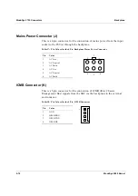
Mains Power Connector (J)
This is a 6-pin connector for the connection of mains power from the input
socket to the PSU(s) through the backplane.
Table 17: Pin Values for the 6-Pin, Backplane Mains Power Connector
Pin
Value
1
AC Live
2
AC Neutral
3
AC Earth
4
AC Live
5
AC Neutral
6
AC Earth
ICMB Connector (K)
This is a 5-pin connector for the connection of ICMB (Inter Chassis
Management Bus) signals from the SBC via the backplane to the external
environment.
Table 18: Pin Values for the 4-Pin, ICMB Connector
Pin
Value
1 GND
2
ICMB RDX
3
ICMB TDX
4
ICMB DE
1
2
3
4
5
6
1
Содержание MODUSYS 2000 Kernel
Страница 5: ......
Страница 9: ......
Страница 11: ......
Страница 13: ......
Страница 17: ......
Страница 21: ......
Страница 25: ......
Страница 26: ...1 Introduction...
Страница 27: ......
Страница 30: ...Introduction Configuration Variants ModuSys 2000 Kernel 1 5 Figure 1 Illustration of the ModuSys 2000...
Страница 50: ...2 Backplane...
Страница 51: ......
Страница 64: ...3 Accessing Internal Components...
Страница 65: ......
Страница 71: ......
Страница 72: ...4 Installing and Removing Storage Devices...
Страница 73: ......
Страница 84: ...5 Installing and Removing Option Boards...
Страница 85: ......
Страница 97: ...Removing an SBC Installing and Removing Option Boards 5 14 ModuSys 2000 Kernel 1 2 Figure 28 Removing an SBC...
Страница 98: ...6 Replacing Module Unit Components...
Страница 99: ......
Страница 104: ...Replacing Module Unit Components Cleaning the Air Filter ModuSys 2000 Kernel 6 7 1 Figure 30 Cleaning the Air Filter...
Страница 108: ...Replacing Module Unit Components Replacing the Power Supply Unit ModuSys 2000 Kernel 6 11...
Страница 109: ......
Страница 110: ...A Assembly Drawings...
Страница 111: ......
Страница 112: ...Assembly Drawings ModuSys 2000 Kernel A 3...
Страница 113: ...Assembly Drawings A 4 ModuSys 2000 Kernel...

