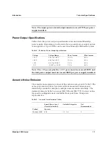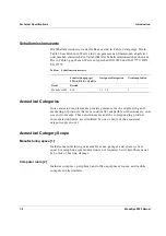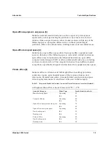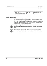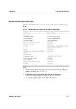
Introduction
Setting Up the Module Unit
ModuSys 2000 Kernel
1-17
3
1
2
Setting Up the Module Unit
This section describes how to set up the module unit. It contains
information on:
•
Rear Panel Ports, Connectors, Controls and Indicators
•
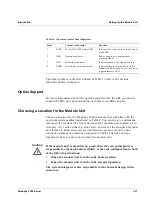
Option Support
•
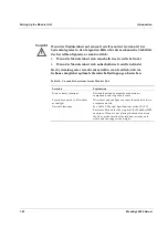
Choosing a Location for the Module Unit
•
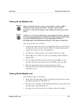
Turning On the Module Unit
•
Turning Off the Module Unit
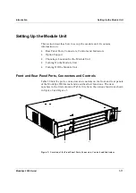
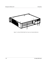
Front and Rear Panel Ports, Connectors and Controls
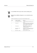
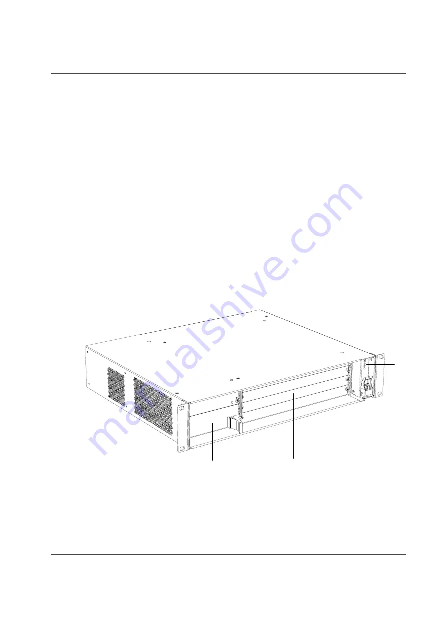
Table 10 lists the ports, connectors and controls on the front and rear panels
of the ModuSys 2000 kernel and describes their functions. The item
numbers in the first column of Table 10 refer to the various functions shown
in Figure 2 and Figure 3.
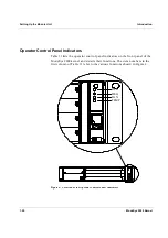
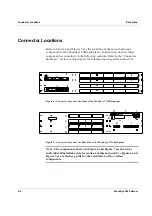
Figure 2: Location of the Front Panel Ports, Connectors, Controls and Indicators
Содержание MODUSYS 2000 Kernel
Страница 5: ......
Страница 9: ......
Страница 11: ......
Страница 13: ......
Страница 17: ......
Страница 21: ......
Страница 25: ......
Страница 26: ...1 Introduction...
Страница 27: ......
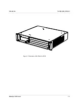
Страница 30: ...Introduction Configuration Variants ModuSys 2000 Kernel 1 5 Figure 1 Illustration of the ModuSys 2000...
Страница 50: ...2 Backplane...
Страница 51: ......
Страница 64: ...3 Accessing Internal Components...
Страница 65: ......
Страница 71: ......
Страница 72: ...4 Installing and Removing Storage Devices...
Страница 73: ......
Страница 84: ...5 Installing and Removing Option Boards...
Страница 85: ......
Страница 97: ...Removing an SBC Installing and Removing Option Boards 5 14 ModuSys 2000 Kernel 1 2 Figure 28 Removing an SBC...
Страница 98: ...6 Replacing Module Unit Components...
Страница 99: ......
Страница 104: ...Replacing Module Unit Components Cleaning the Air Filter ModuSys 2000 Kernel 6 7 1 Figure 30 Cleaning the Air Filter...
Страница 108: ...Replacing Module Unit Components Replacing the Power Supply Unit ModuSys 2000 Kernel 6 11...
Страница 109: ......
Страница 110: ...A Assembly Drawings...
Страница 111: ......
Страница 112: ...Assembly Drawings ModuSys 2000 Kernel A 3...
Страница 113: ...Assembly Drawings A 4 ModuSys 2000 Kernel...

