ModuSys 2000 Kernel
ix
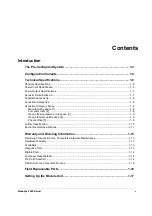
Tables
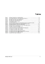
Table 1:
Sellable Part Numbers for ModuSys2000 ..............................................................................1-4
Table 2:
Physical Specifications of the ModuSys2000 Enclosure........................................................1-6
Table 3:
ModuSys 2000 Power Input Specifications ............................................................................1-6
Table 4:
ModuSys Power Output Specifications ..................................................................................1-7
Table 5:
Acoustic Noise Emission Values ............................................................................................1-7
Table 6:
Schallemissionswerte .............................................................................................................1-8
Table 7:
Required Limits for Product Acoustical Noise Emission (Corrected Declared)......................1-9
Table 8:
Environmental Specifications for the ModuSys2000 Enclosure...........................................1-11
Table 9:
Reliability Estimates for ModuSys 2000 Kernels..................................................................1-12
Table 10:
Rear Panel Ports, Connectors and Controls for ModuSys Kernel .......................................1-19
Table 11:
Operator Control Panel Indicators ........................................................................................1-21
Table 12:
Unsuitable Locations for the Module Unit.............................................................................1-22
Table 13:
Summary of Connectors on the ModuSys 2735 Backplane...................................................2-5
Table 14:
Pin Values for the 20-Pin OCP Connector ...........................................................................2-12
Table 15:
Pin Values for the 20-Pin OCP Connector ...........................................................................2-13
Table 16:
Pin Values for the 4-Pin, Drive Power Connector ................................................................2-13
Table 17:
Pin Values for the 6-Pin, Backplane Mains Power Connector .............................................2-14
Table 18:
Pin Values for the 4-Pin, ICMB Connector ...........................................................................2-14
Table 19:
Supported Drive Bay Configurations ......................................................................................4-3
Содержание MODUSYS 2000 Kernel
Страница 5: ......
Страница 9: ......
Страница 11: ......
Страница 13: ......
Страница 17: ......
Страница 21: ......
Страница 25: ......
Страница 26: ...1 Introduction...
Страница 27: ......
Страница 30: ...Introduction Configuration Variants ModuSys 2000 Kernel 1 5 Figure 1 Illustration of the ModuSys 2000...
Страница 50: ...2 Backplane...
Страница 51: ......
Страница 64: ...3 Accessing Internal Components...
Страница 65: ......
Страница 71: ......
Страница 72: ...4 Installing and Removing Storage Devices...
Страница 73: ......
Страница 84: ...5 Installing and Removing Option Boards...
Страница 85: ......
Страница 97: ...Removing an SBC Installing and Removing Option Boards 5 14 ModuSys 2000 Kernel 1 2 Figure 28 Removing an SBC...
Страница 98: ...6 Replacing Module Unit Components...
Страница 99: ......
Страница 104: ...Replacing Module Unit Components Cleaning the Air Filter ModuSys 2000 Kernel 6 7 1 Figure 30 Cleaning the Air Filter...
Страница 108: ...Replacing Module Unit Components Replacing the Power Supply Unit ModuSys 2000 Kernel 6 11...
Страница 109: ......
Страница 110: ...A Assembly Drawings...
Страница 111: ......
Страница 112: ...Assembly Drawings ModuSys 2000 Kernel A 3...
Страница 113: ...Assembly Drawings A 4 ModuSys 2000 Kernel...


