Содержание MODUSYS 2000 Kernel

Страница 1: ...ed and idle equipment along with credit for buybacks and trade ins Custom engineering so your equipment works exactly as you specify Critical and expedited services Leasing Rentals Demos In stock Read...

Страница 2: ...MODUSYS 2000 Kernel OEM Information for the 2U cPCI Enclosure P N 217540 Revision A1 August 2002 DRAFT EK A1057 UG Rev A1...

Страница 3: ...itten consent of Force Computers GmbH Force Computers GmbH assumes no responsibility for the use of any circuitry other than circuitry that is part of a product of Force Computers GmbH Force Computers...

Страница 4: ...icas Europe Asia Force Computers Inc 4305 Cushing Parkway Fremont CA 94538 U S A Tel 1 510 445 6000 Fax 1 510 445 3382 Email support fci com Force Computers GmbH Lilienthalstrasse 15 D 85579 Neubiberg...

Страница 5: ......

Страница 6: ...facturing space 1 1 8 Computer room 2 1 8 Open office equipment only space 3 1 9 Open office occupied space 4 1 9 Private office 5 1 9 Airflow Specification 1 10 Environmental Specifications 1 11 Warr...

Страница 7: ...uSys 2735 Connectors 2 6 Positronic Power Connector A 2 6 CPCI Connectors B C D E 2 7 Connectors B J1 and J2 2 7 Connectors B J3 2 8 Connectors B J4 2 9 Connectors B J5 2 10 20 Pin OCP Connector F 2 1...

Страница 8: ...to a Front Access Drive Bay 4 11 Cable Routing to the Front Access Drive Bay 4 12 Installing and Removing Option Boards Option Board Configurations 5 3 Installing cPCI and PMC Option Boards 5 5 Removi...

Страница 9: ......

Страница 10: ...0 Enclosure 1 11 Table 9 Reliability Estimates for ModuSys 2000 Kernels 1 12 Table 10 Rear Panel Ports Connectors and Controls for ModuSys Kernel 1 19 Table 11 Operator Control Panel Indicators 1 21 T...

Страница 11: ......

Страница 12: ...12 B J5 Connector Pinout Rows A C 2 11 Figure 13 B J5 Connector Pinout Rows D E 2 11 Figure 14 Location of Pins on the OCP Connector 2 11 Figure 15 Location of Pins on the OCP Connector 2 12 Figure 1...

Страница 13: ......

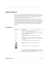
Страница 14: ...ption n nn A period in numerals signals the decimal point indicator For example 1 75 equals one and three fourths nn nnn A space character separates digits in numerals with 5 or more digits For exampl...

Страница 15: ...ual User information manuals accompanying each Single Board Computer SBC Consult these manuals for more information on the SBC firmware and supported options For More Information If you need help with...

Страница 16: ...y and operator control panel OCP A kernel does not contain either an SBC or specified storage devices Module unit In this manual the term module unit refers to a module unit assembled from a backplane...

Страница 17: ......

Страница 18: ...d to install maintain and operate the ModuSys kernel The information given in this manual is meant to complete the knowledge of a specialist and must not be taken as replacement for qualified personne...

Страница 19: ...Voluntary Control Council for Interference by Information Technology Interference VCCI If this equipment is used in a domestic environment radio disturbance may arise When such trouble occurs the user...

Страница 20: ...to open the system To avoid electric shock when opening the chassis it is not sufficient to switch off the main function switch because it does not remove the AC line voltage from the system Therefor...

Страница 21: ......

Страница 22: ...t werden Einbau Wartung und Betrieb d rfen nur von durch Force Computers ausgebildetem oder im Bereich Elektronik oder Elektrotechnik qualifiziertem Personal durchgef hrt werden Die in diesem Handbuch...

Страница 23: ...n wenden Sie sich an Ihren Vertreter von Force Computers VCCI Das ModuSys Kernel ist ein Ger t der Klasse B gem dem Standard des Voluntary Control Council for Interference von Information Technology I...

Страница 24: ...orce Computers ausgebildetem oder im Bereich Elektronik oder Elektrotechnik qualifiziertem Personal ge ffnet werden Um einen elektrischen Schlag beim ffnen des Systems zu vermeiden gen gt es nicht das...

Страница 25: ......

Страница 26: ...1 Introduction...

Страница 27: ......

Страница 28: ...y 2U system which includes integral fan assembly using three axial fans for cooling an operator control panel OCP and a 200W power supply unit PSU An option of power supply redundancy is available by...

Страница 29: ...1 lists the part numbers you can order for the 2U cPCI enclosure Note Please refer to the separate CPU User Manual for associated information Table 1 Sellable Part Numbers for ModuSys2000 Part Number...

Страница 30: ...Introduction Configuration Variants ModuSys 2000 Kernel 1 5 Figure 1 Illustration of the ModuSys 2000...

Страница 31: ...nclosure Table 2 Physical Specifications of the ModuSys2000 Enclosure Specification ModuSys Kernel Weight kg lb 10kg 22lbs Height cm in 88 36mm 3 48 2U Width cm in 437 8mm 17 24 Depth cm in 380 0mm 14...

Страница 32: ...1 4 V to 12 60 V 5 5 A 0 2 A 12 V 13 20 V to 10 8 V 1 5 A 0 0 A Note The 5 V power plus the 3 3 V power must not exceed 200 W and the total power output must not exceed 200W per power supply installed...

Страница 33: ...r t Betrieb ModuSys2000 43 8 1 2 3 4 5 Acoustical Categories Noise emission requirements provide guidance for the engineering and marketing of products that are acoustically compatible with customers...

Страница 34: ...essional work areas including co located output devices This category includes all open office products except those specifically designed and marketed for equipment only spaces Private office 5 Inclu...

Страница 35: ...static pressure The calculated airflow though the enclosure is in excess of 250 lfm although the actual airflow volume through the enclosure is reduced depending on the selected SBC and options and th...

Страница 36: ...C 82 F Minimum dew point 2 C 36 F Vibration 5 Hz to 10 Hz 0 020in 0 5mm 10 Hz to 500 Hz to 10 Hz 0 1 G peak Shock 10 G 3 axis MTBF Estimate Telcordia Issue 6 Method 1 case 3 See Table 9 Nonoperating...

Страница 37: ...eliability at 50 C 1 Air temperatures are inlet ambient to the ModuSys enclosure These estimates are provided to assist in maintenance planning they do not supersede or affect the published warranty T...

Страница 38: ...of return to Force Computers Repair Service Center Force will at it s option repair replace or provide a credit for defective FRUs that are returned to Force under the warranty program For repairs For...

Страница 39: ...in transit to Force Computers Pre Call Checklist Prior to calling Force Computers or an authorized reseller please follow the pre call checklist This allows Force Computers to assist you more quickly...

Страница 40: ...1 15 which would normally be as defined below The Customer is responsible for sending the product to the address provided The Customer pays for transportation for Return to Force warranty to the fact...

Страница 41: ...ble Parts Introduction 1 16 ModuSys 2000 Kernel Field Replaceable Parts For field replaceable parts associated with the ModuSys 2000 enclosure and module unit please refer requests to your local Force...

Страница 42: ...ocation for the Module Unit Turning On the Module Unit Turning Off the Module Unit Front and Rear Panel Ports Connectors and Controls Table 10 lists the ports connectors and controls on the front and...

Страница 43: ...Setting Up the Module Unit Introduction 1 18 ModuSys 2000 Kernel 4 5 2 Figure 3 Location of the Rear Panel Ports Connectors Controls and Indicators...

Страница 44: ...Supply Drive Bays Available for additional removable power supplies 2 Option slots Depending on the options installed these slots may contain various ports connectors controls or indicators See your...

Страница 45: ...able 11 lists the operator control panel indicators on the front panel of the ModuSys 2000 kernel and details their functions The item numbers in the first column of Table 11 refer to the various func...

Страница 46: ...your SBC supplier Choosing a Location for the Module Unit Choose a location for the ModuSys 2000 enclosure that complies with the environmental specifications listed in Table 8 You must leave a minimu...

Страница 47: ...tlich da im Geh use m glichst optimale thermische Bedingungen herrschen Table 12 Unsuitable Locations for the Module Unit Location Explanation Dirty or dusty locations Dirt and dust can damage the mod...

Страница 48: ...herals that are connected to the module unit to ensure that you follow the appropriate power sequencing procedure for each peripheral 2 Set the power switch on the rear of the module unit to ON 3 When...

Страница 49: ...ly range allows systems designers to use a variety of low cost high performance peripherals The Force Computers ModuSys Product Family of enclosures can accommodate a variety of SBCs and supports mult...

Страница 50: ...2 Backplane...

Страница 51: ......

Страница 52: ...iagram of the connections between the main functional components It shows the main connections from Compact PCI backplane within the ModuSys2000 kernel Figure 5 Functional Block Diagram of the ModuSys...

Страница 53: ...n the following sections Refer to the Connector Summary section in this chapter for information on specific connectors Figure 6 Connector Layout of the Front of the ModuSys 2735 Backplane Figure 7 Con...

Страница 54: ...s refer to Compact PCI spec Table 13 Summary of Connectors on the ModuSys 2735 Backplane Connector Description Page A Positronic Power Connector 2 6 B cPCI Connectors SBC Slot 2 7 C cPCI Connectors Op...

Страница 55: ...Server Management Connector G Drive Power Connector H IDE Data Connector I Mains Power Connector J ICMB Connector K Positronic Power Connector A The Positronic connector is a standard power connector...

Страница 56: ...J4 and J5 These correspond with signals on the cPCI connectors B on the backplane Figure 9 Location of SBC CompactPCI Connectors Top View Connectors B J1 and J2 The B J1 and J2 connectors implement th...

Страница 57: ...lane 2 8 ModuSys 2000 Kernel Connectors B J3 The B J3 provides interfaces to Ethernet signals ETHx reserved_2 16 for PICMG 2 16 and RTB PMC1 I O PMC1IO_ Rear transition board information block RIB_ Fi...

Страница 58: ...Backplane ModuSys 2735 Connectors ModuSys 2000 Kernel 2 9 Connectors B J4 The connectors B J3 provides interfaces to Parallel LPT_ PMC 2 I O PMC2IO_ COM3 COM3_ Figure 11 B J4 Connector Pinout...

Страница 59: ...duSys 2735 Connectors Backplane 2 10 ModuSys 2000 Kernel Connectors B J5 The B J5 provides interfaces to Secondary IDE IDE_ USB USB_ keyboard KBD PS2 mouse MS COM1 COM1_ COM2 COM2_ floppy FD_ IPMB ICM...

Страница 60: ...perator Control Panel connector allows a single connection to be made to a purpose designed operator control panel This connection includes signals from the following Fan Status Power Status Over Temp...

Страница 61: ...ser 1 13 Backplane SM_CLK 14 User 2 15 Backplane Data 16 PSU Degrade Signal 17 DC Enable 18 Soft ON 19 GND 20 GND 20 Pin Server Management Connector G The 26 pin OCP connector allows a single connecti...

Страница 62: ...5 Backplane Data 16 Soft ON 17 PSU 2 Degrade Signal 18 PSU 1 Degrade Signal 19 PSU 3 Degrade Signal 20 No Connection 21 PSU 3 Fail Signal 22 PSU 1 Fail Signal 23 No Connection 24 PSU 2 Fail Signal 25...

Страница 63: ...in Values for the 6 Pin Backplane Mains Power Connector Pin Value 1 AC Live 2 AC Neutral 3 AC Earth 4 AC Live 5 AC Neutral 6 AC Earth ICMB Connector K This is a 5 pin connector for the connection of I...

Страница 64: ...3 Accessing Internal Components...

Страница 65: ......

Страница 66: ...s Internal Components Before you remove the module unit cover follow these steps 1 Shut down the operating system following the instructions in the operating system documentation 2 Set the power switc...

Страница 67: ...strap Antistatic Precautions Force recommends that you use an antistatic wrist strap when handling internal components In addition follow these rules Do not allow any circuit board or component to tou...

Страница 68: ...unit is installed in the rack frame It is largely depending on the location and available access to areas of the rack mounted system whether it is necessary to remove the system from the rack frame Th...

Страница 69: ...nicht kippt To dismount the module unit carry out the following steps 1 Remove all cables from the rear of the module unit 2 Ensure that all other equipment installed in the rack is fully pushed back...

Страница 70: ...y reversing the steps in the section Dismounting the Module Unit in this chapter 6 Reconnect any of the external cables that were disconnected from the module unit 7 Set the power switches to the ON p...

Страница 71: ......

Страница 72: ...4 Installing and Removing Storage Devices...

Страница 73: ......

Страница 74: ...for storage devices in the enclosure Table 19 list s the devices supported in the enclosure Table 19 Supported Drive Bay Configurations Drive Bays Supported Devices Rear internal drive bay 1 One 1 0 I...

Страница 75: ...Drive Bays Installing and Removing Storage Devices 4 4 ModuSys 2000 Kernel 2 Figure 17 Optional Front Drive Bay Location...

Страница 76: ...Chapter 3 to dismount the module unit from a rack if additional access is required 2 Ensure that the mains power cable has been removed from the rear of the module unit 3 Unscrew the four screws 1 th...

Страница 77: ...ke anti ESD precautions such as wearing isolation gloves or an antistatic wriststrap Vorsicht Vorsicht im Umgang mit dem Speicherlaufwerkger t Die aktiven Bauteile auf dem Speicherlaufwerkger t d rfen...

Страница 78: ...Installing and Removing Storage Devices Removing an Internal Disk Drive ModuSys 2000 Kernel 4 7 8 3 4 6 7 Figure 19 Rear Access Disk Drive Assembly...

Страница 79: ...Drive Installing and Removing Storage Devices 4 8 ModuSys 2000 Kernel Installing an Internal Disk Drive To install a storage device in the internal disk drive bay reverse the steps in the section Remo...

Страница 80: ...onal access is required 2 Unscrew the two captive fasteners 1 and pull the drive assembly forwards to remove it from the enclosure drive bay 3 With the drive assembly exposed remove the power and data...

Страница 81: ...ng mit dem Speicherlaufwerkger t Die aktiven Bauteile auf dem Speicherlaufwerkger t d rfen keiner elektrostatischen Entladung ESD ausgesetzt sein und k nnen leicht besch digt werden Bitte treffen Sie...

Страница 82: ...ont Access Drive Bay To install a storage device into a front access drive bay reverse the steps in the section Removing a Drive from the Front Access Drive Bay Ensure that where the floppy or similar...

Страница 83: ...rive bay Figure 21 shows a diagram of the suggested routing of cables over the top of the backplane for front mounted storage devices in the ModuSys kernel This cable route provides efficient routing...

Страница 84: ...5 Installing and Removing Option Boards...

Страница 85: ......

Страница 86: ...uate airflow provision and any other matters You can install various combinations of cPCI option boards onto the Force Computers ModuSys Product Family backplane 1 Installation of the SBC can only be...

Страница 87: ...nfigurations Installing and Removing Option Boards 5 4 ModuSys 2000 Kernel SBC Figure 22 SBC Connector Location on the Backplane Note The illustrations in this chapter show a typical backplane for ref...

Страница 88: ...You must select a connector that is appropriate for the type of option board that you are installing 6 Carefully slide the option board 1 into the appropriate connector on the Force Computers ModuSys...

Страница 89: ...dem Speicherlaufwerkger t Die aktiven Bauteile auf dem Speicherlaufwerkger t d rfen keiner elektrostatischen Entladung ESD ausgesetzt sein und k nnen leicht besch digt werden Bitte treffen Sie Vorkehr...

Страница 90: ...Installing and Removing Option Boards Installing cPCI and PMC Option Boards ModuSys 2000 Kernel 5 7 1 2 Figure 24 Installing an RTM Option Board...

Страница 91: ...the option board 1 3 Disconnect any cables connected to the internal or external ports on the option board 4 Disengage the two retaining locks 2 securing the option board to the chassis 5 Carefully d...

Страница 92: ...dem Speicherlaufwerkger t Die aktiven Bauteile auf dem Speicherlaufwerkger t d rfen keiner elektrostatischen Entladung ESD ausgesetzt sein und k nnen leicht besch digt werden Bitte treffen Sie Vorkehr...

Страница 93: ...Removing cPCI and PMC Option Boards Installing and Removing Option Boards 5 10 ModuSys 2000 Kernel 1 2 Figure 26 Removing an RTM Option Board...

Страница 94: ...fitted from the chassis and store it for future use 5 Carefully install the SBC 1 in the correct connector on the backplane Depending on the SBC you may wish to connect some PMC options before install...

Страница 95: ...g mit der SBC Platte Die aktiven Bauteile auf der SBC Platte d rfen keiner elektrostatischen Entladung ESD ausgesetzt sein und k nnen leicht besch digt werden Bitte treffen Sie Vorkehrungen gegen ESD...

Страница 96: ...ou may wish to remove some cables after removing the SBC from the backplane 4 Disengage the two retaining locks 2 that secure the SBC to the chassis 5 Carefully remove the SBC from the SBC connector o...

Страница 97: ...Removing an SBC Installing and Removing Option Boards 5 14 ModuSys 2000 Kernel 1 2 Figure 28 Removing an SBC...

Страница 98: ...6 Replacing Module Unit Components...

Страница 99: ......

Страница 100: ...Please refer to this section for information on removing or replacing either of these components Remove the fan assembly follows see Figure 29 1 Follow the instructions in Chapter 3 to dismount the m...

Страница 101: ...le Unit Components 6 4 ModuSys 2000 Kernel 1 3 2 4 Figure 29 Removing the Fan Assembly Note Figure 29 illustrates the removal and replacement of a typical fan If there is a fan safety guard then repla...

Страница 102: ...mu nach dem Ersetzen der R ckplatte wieder angeschlossen werden Der Betrieb des K hlgebl ses mu unmittelbar nach dem Einschalten des Stromes berpr ft werden Falls das K hlgebl se nicht richtig wieder...

Страница 103: ...h which you need to clean the air filter depends on local conditions Clean the air filter in the ModuSys2000 enclosure as follows see Figure 30 1 Refer to the previous section on Removing the fan asse...

Страница 104: ...Replacing Module Unit Components Cleaning the Air Filter ModuSys 2000 Kernel 6 7 1 Figure 30 Cleaning the Air Filter...

Страница 105: ...bevor Sie fortfahren Caution Power Supply Service Personnel should note that the power supply contains double pole fusing Vorsicht Wartungspersonal sollte beachten da die Spannungsquelle zweipolig ge...

Страница 106: ...Replacing Module Unit Components Removing the Power Supply Unit ModuSys 2000 Kernel 6 9 1 2 Figure 31 Removing the Power Supply Unit from the ModuSys Kernel...

Страница 107: ...ower Supply Unit Danger Make sure that the mains power supply is disconnected from the module unit before continuing Gefahr Bitte trennen Sie die Moduleinheit von der Spannungsversorgung bevor Sie for...

Страница 108: ...Replacing Module Unit Components Replacing the Power Supply Unit ModuSys 2000 Kernel 6 11...

Страница 109: ......

Страница 110: ...A Assembly Drawings...

Страница 111: ......

Страница 112: ...Assembly Drawings ModuSys 2000 Kernel A 3...

Страница 113: ...Assembly Drawings A 4 ModuSys 2000 Kernel...

Страница 114: ...uipment Have surplus equipment taking up shelf space We ll give it a new home Learn more Visit us at artisantg com for more info on price quotes drivers technical specifications manuals and documentat...

Отзывы: